Wiring Lcd I2c Arduino

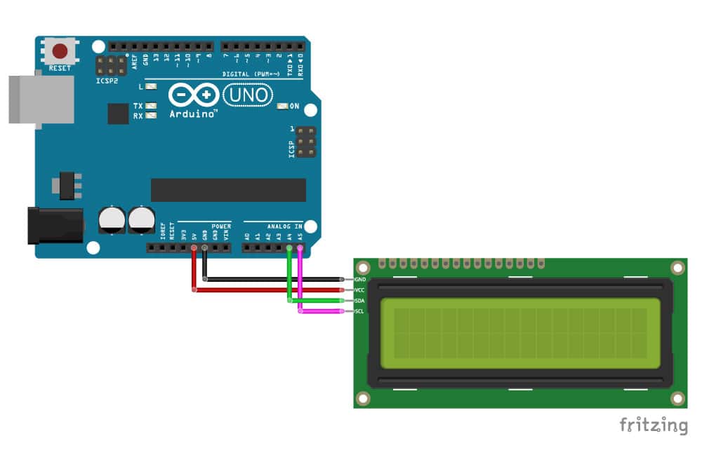
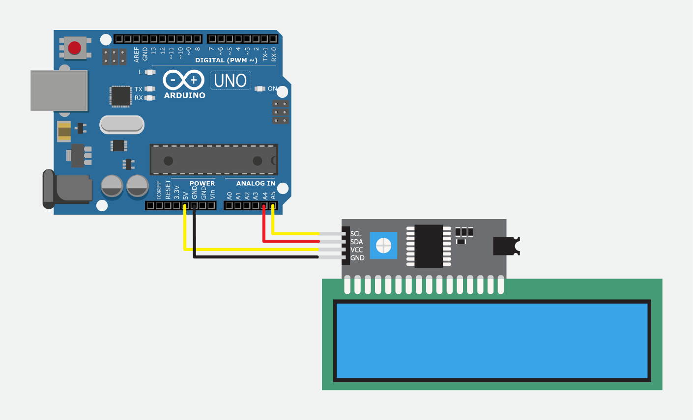
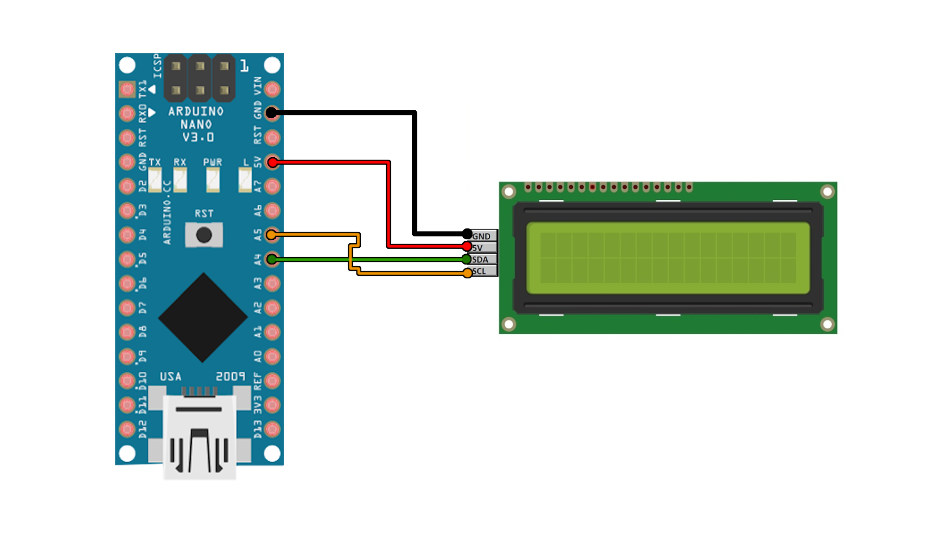
In Depth Interfacing An I2c Lcd With Arduino About lcd i2c 16x2. in the previous tutorial, we had learned how to use the normal lcd. however, wiring between arduino and the normal lcd is complicated. therefore, lcd i2c has been created to simplify the wiring. actually, lcd i2c is composed of a normal lcd, an i2c module and a potentiometer. pinout. lcd i2c uses i2c interface, so it has 4 pins:. On the i2c module, you will find a potentiometer that you can turn with a small screwdriver. plug in the usb connector of the arduino to power the lcd. you should see the backlight light up. now rotate the potentiometer until one (16×2 lcd) or 2 rows (20×4 lcd) of rectangles appear.

Character I2c Lcd With Arduino Tutorial 8 Examples Scl is the i2c clock pin. wiring an i2c lcd display to an arduino. connecting an i2c lcd is much simpler than connecting a standard lcd. you only need to connect four pins. begin by connecting the vcc pin to the arduino’s 5v output and the gnd pin to ground. now we are left with the pins that are used for i2c communication. This is a comprehensive guide for arduino i2c lcd 16×2 interfacing. you’ll learn how to use i2c lcd with arduino and create some example projects to practice what we’ll be learning in this tutorial. we’ll implement the following examples in this tutorial: arduino i2c lcd 16×2 text variables display. arduino i2c lcd 16×2 scrolling. I2c lcd adapter. the core of the adapter features an 8 bit i o expander chip – pcf8574. this chip transforms the i2c data from an arduino into the parallel data necessary for an lcd display. the board is equipped with a small trimpot for precise adjustments to the display’s contrast. a jumper on the board supplies power to the backlight. You will need to know the actual address of the lcd before you can start using it. we have a simple arduino sketch that scans the i2c bus and displays the i2c address of any devices in the serial monitor. use the sketch below and turn on the serial monitor (keyboard shortcut of ctrl shift m). 1. 2.

How To Interface Lcd With Arduino Using I2c Module I2c lcd adapter. the core of the adapter features an 8 bit i o expander chip – pcf8574. this chip transforms the i2c data from an arduino into the parallel data necessary for an lcd display. the board is equipped with a small trimpot for precise adjustments to the display’s contrast. a jumper on the board supplies power to the backlight. You will need to know the actual address of the lcd before you can start using it. we have a simple arduino sketch that scans the i2c bus and displays the i2c address of any devices in the serial monitor. use the sketch below and turn on the serial monitor (keyboard shortcut of ctrl shift m). 1. 2. Before wiring the lcd screen to your arduino board we suggest to solder a pin header strip to the 14 (or 16) pin count connector of the lcd screen, as you can see in the image further up. to wire your lcd screen to your board, connect the following pins: lcd rs pin to digital pin 12; lcd enable pin to digital pin 11; lcd d4 pin to digital pin 5. The arduino built in wire.h library for i2c communication enables the internal pullup resistors for both sda & scl lines. the internal pullup resistors (rpu= 20~50kΩ) are pretty much weak and not sufficient. therefore, you can manually disable them in code, and connect your external i2c pullup resistors.

I2c Lcd Arduino Library Tutorial Before wiring the lcd screen to your arduino board we suggest to solder a pin header strip to the 14 (or 16) pin count connector of the lcd screen, as you can see in the image further up. to wire your lcd screen to your board, connect the following pins: lcd rs pin to digital pin 12; lcd enable pin to digital pin 11; lcd d4 pin to digital pin 5. The arduino built in wire.h library for i2c communication enables the internal pullup resistors for both sda & scl lines. the internal pullup resistors (rpu= 20~50kΩ) are pretty much weak and not sufficient. therefore, you can manually disable them in code, and connect your external i2c pullup resistors.

I2c Module With Lcd Display Using Arduino Circuits4you

Comments are closed.