Wiring Diagram Engine Coolant

Wiring Diagram Engine Coolant Overall, understanding the coolant temperature gauge wiring is essential for monitoring the engine’s temperature and ensuring the proper functioning of your vehicle’s cooling system. by familiarizing yourself with the wiring diagram and properly maintaining the wiring connections, you can help prevent overheating issues and keep your car running smoothly. The engine coolant temperature sensor (ect) wiring diagram serves two main purposes: it provides a reliable source of signal information that allows you to monitor the temperature of your engine coolant fluid, and it ensures that the proper wattage is being used to power the sensor's electrical components. the wiring diagram consists of several.

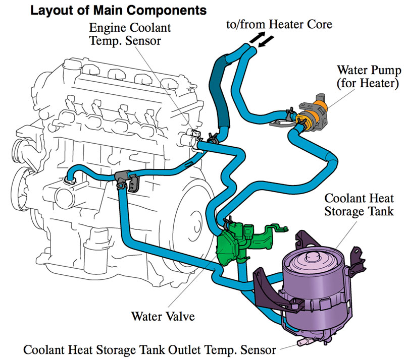
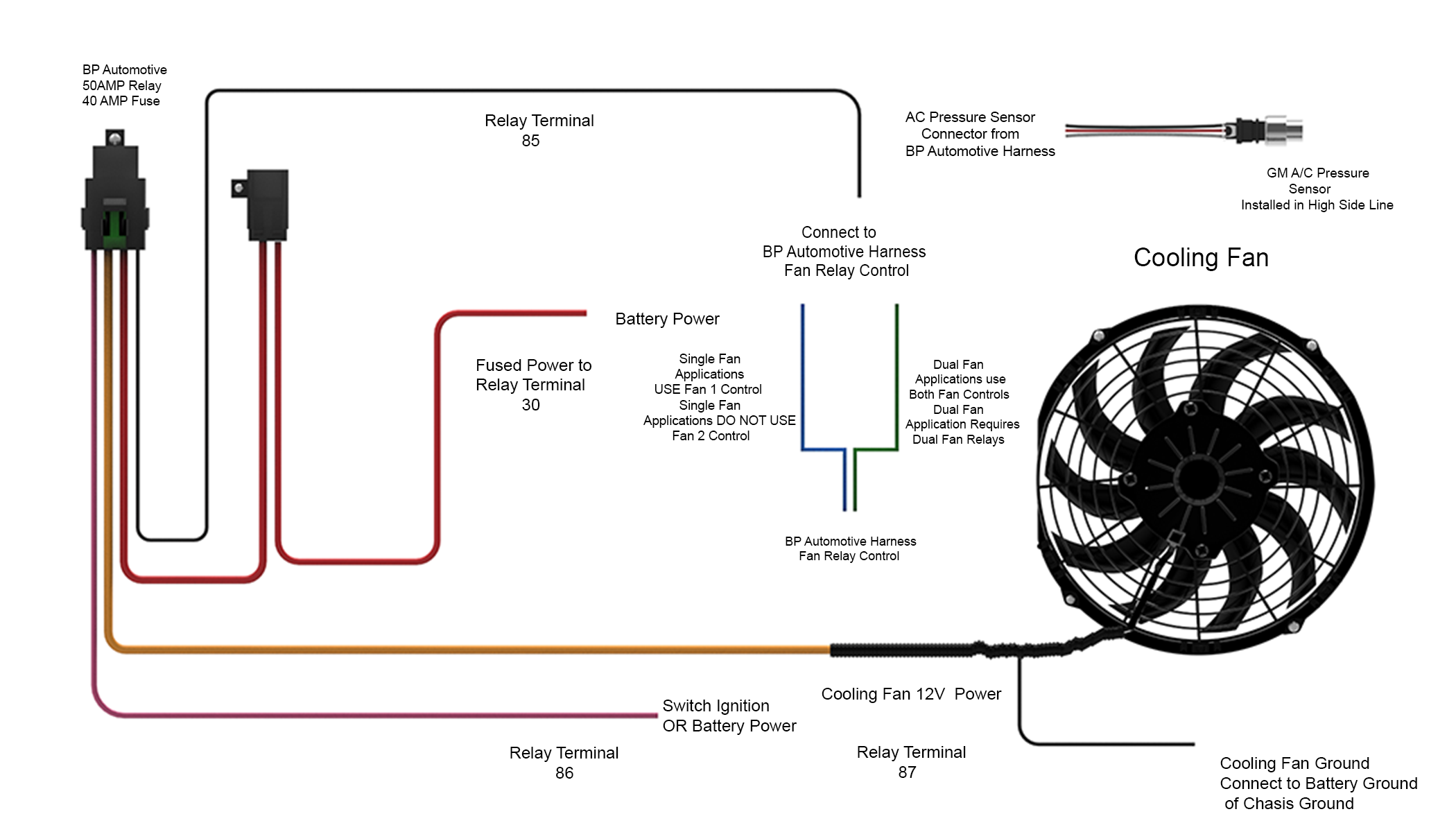
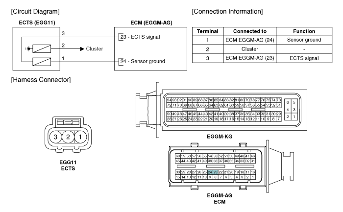
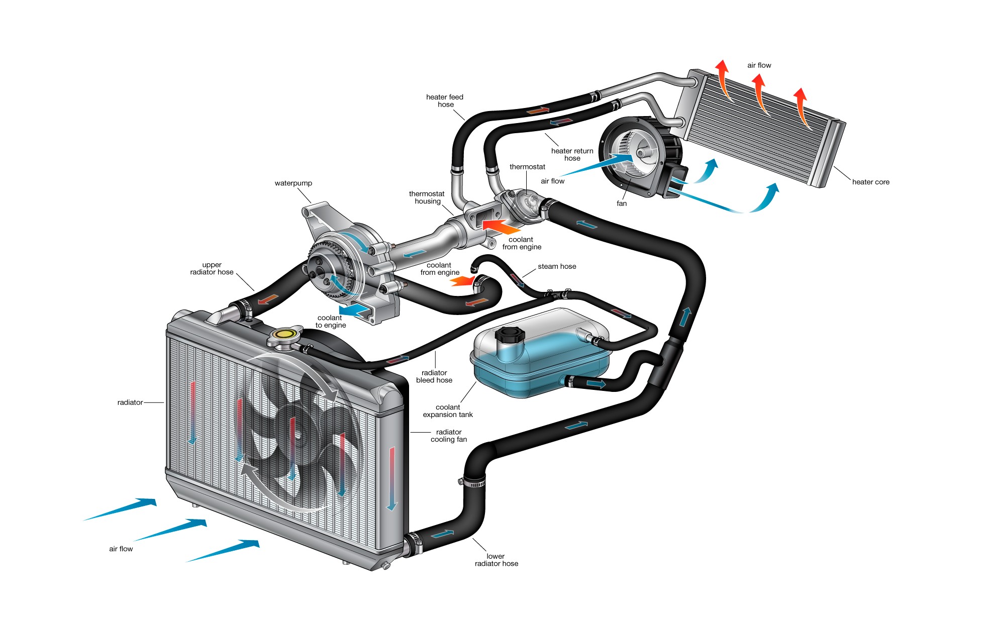
Engine Cooling Fan Wiring Diagram 3 wire coolant temperature sensor wiring diagram. the two wires, a “5 volt reference”, and a “ground wire” go to the ecu, and the third wire “earth 1 wire for temp gauge” goes to the cluster mounted temperature gauge by providing an earth link to the temperature gauge. in three wire coolant temp sensors, the ecu does not control the. A coolant system diagram is a visual representation of the components and flow path of a cooling system in an engine. the cooling system plays a crucial role in maintaining the temperature of an engine and preventing overheating. it circulates a liquid coolant through the engine, absorbs heat from the various components, and dissipates it into. The wiring diagram for the engine coolant temperature sensor typically includes three wires: a power supply wire, a ground wire, and a signal wire. the power supply wire provides voltage to the sensor, while the ground wire completes the circuit. the signal wire carries the temperature data from the sensor to the ecu. A typical engine cooling temperature sensor is a negative temperature coefficient (ntc) thermistor, which means its electrical resistance decreases when the temperature increases. the tip of the ect sensor protrudes into one of the cooling system passages and is immersed in coolant. many cars have more than one coolant temperature sensor.

Engine Coolant Temperature Sensor Wiring Diagram Wiring Digital And The wiring diagram for the engine coolant temperature sensor typically includes three wires: a power supply wire, a ground wire, and a signal wire. the power supply wire provides voltage to the sensor, while the ground wire completes the circuit. the signal wire carries the temperature data from the sensor to the ecu. A typical engine cooling temperature sensor is a negative temperature coefficient (ntc) thermistor, which means its electrical resistance decreases when the temperature increases. the tip of the ect sensor protrudes into one of the cooling system passages and is immersed in coolant. many cars have more than one coolant temperature sensor. When it comes to understanding the wiring diagram for a 3 wire coolant level sensor, careful decoding is required. this sensor plays a crucial role in monitoring the coolant level in an engine, allowing for efficient temperature regulation. by examining the wiring diagram, one can gain insight into how the sensor is connected and how it. The ls engine coolant flow diagram is an essential part of understanding how the cooling system in an ls engine works. this diagram shows the path that coolant takes through the engine, from the radiator to the water pump and back again. understanding this flow is crucial for diagnosing any cooling system problems and ensuring that the engine.

Coolant System Diagram My Wiring Diagram When it comes to understanding the wiring diagram for a 3 wire coolant level sensor, careful decoding is required. this sensor plays a crucial role in monitoring the coolant level in an engine, allowing for efficient temperature regulation. by examining the wiring diagram, one can gain insight into how the sensor is connected and how it. The ls engine coolant flow diagram is an essential part of understanding how the cooling system in an ls engine works. this diagram shows the path that coolant takes through the engine, from the radiator to the water pump and back again. understanding this flow is crucial for diagnosing any cooling system problems and ensuring that the engine.

Comments are closed.