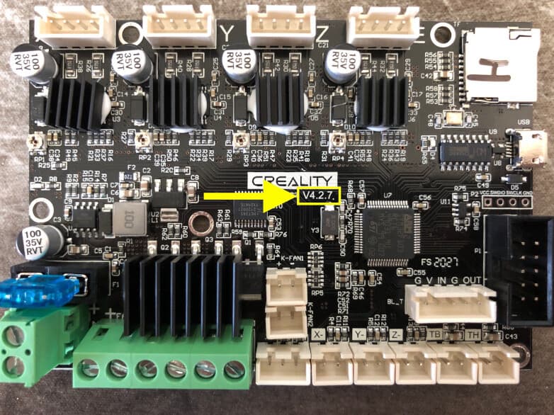
What Is The 4pin Connector Next To This Usb On The Creality 4 2 3 Board

What Is The 4pin Connector Next To This Usb On The Creality 4 2 3 Board Can you add a photo that shows the silk screen next to the 4 pin header, so turn the board 180° clockwise. this is most probably a header for the usb. so you can either use the micro usb or the 4 pin header. $\endgroup$ –. What might these 4 pins be on the creality 4.2.3 board be? the silkscreen says. g sc sd v it is next to the pin header for the lcd, so i suspect it is either a uart or tft port. googling i suspect sd might be short for sda and sc might be short for scl. which are common i2c pin descriptions.

Creality 4 2 2 Board Pin Diagram Iii. connectors and ports symphony. the creality 4.2.7 board boasts a symphony of connectors and ports, each playing a crucial role in the harmonious functioning of your 3d printer. a. usb, sd card, and display connectors. usb connector: serving as a data lifeline, the usb connector facilitates communication between your computer and the 3d. Very cool find here: ender 3 v2 schematic for 4.2.2 board · discussion #814 · jyers marlin · github pdfs also attached here for reference creality.4.2.2. .schematic.28 5 22.pdf (188.1 kb) creality.4.2.7. .schematic.28 5 22 1.pdf (193.7 kb) in addition the 4.2.2 board apparently can come with different driver chips: creality v4.2.x board driver codes the letters written on the card reader. I just need a 3 pin connector for the 4.2.2 main board (ender 3 v2). but i don't know what size they are. bought some off of amazon but they were too small. i'm just trying to connect my ad hoc filament runout sensor. the socket on the main board has three pins. my sensor will use the 1st and third pins. but i need a connector to plug it in. The wiring diagram of the creality 4.2.2 board provides a visual representation of how the various components of the printer are connected to the board. it shows the connections for the power supply, stepper motors, endstop switches, thermistors, and other components. each connection is labeled with a specific pin number, making it easy to.

Creality V4 2 2 Wiring Diagram I just need a 3 pin connector for the 4.2.2 main board (ender 3 v2). but i don't know what size they are. bought some off of amazon but they were too small. i'm just trying to connect my ad hoc filament runout sensor. the socket on the main board has three pins. my sensor will use the 1st and third pins. but i need a connector to plug it in. The wiring diagram of the creality 4.2.2 board provides a visual representation of how the various components of the printer are connected to the board. it shows the connections for the power supply, stepper motors, endstop switches, thermistors, and other components. each connection is labeled with a specific pin number, making it easy to. Works for me. ender 3 pro with crtouch board v4.2.2 chip gd32f303 ret6 is simple, just follow this: this file contains pin mappings for the stock 2020 creality ender 3. pro with the 32 bit creality 4.2.2 board. to use this config, during “make menuconfig” select the stm32f103 with a “28kib bootloader” and serial (on usart1 pa10 pa9. Intro creality v4.2.2, v4.2.3, v4.2.7 & v4.3.1 boards have a dedicated 5 pin header on the board that can be used for the creality bl touch kits. you can also use 3 of those pins and the z endstop port if you have the 3 2 pin wiring harness. our unified 2 firmware is set up to […].

Comments are closed.