What Is A Ballast Resistor In Ignition Wiring Work

Ignition Coil Wiring With Ballast Resistor Basic function: the ballast resistor is a resistor contained in the primary ignition circuit wiring that lowers voltage after the engine is started to reduce wear on ignition components. less well understood is the fact that ballast resistors provide appropriate compensation within a circuit for external demands placed on that circuit. A ballast resistor is used in a device to compensate for changes and secure the other components of a network. when the current flowing through the resistor increase, the temperature also increases. and due to the temperature rise, the resistance also increases. therefore, an increase in resistance limits the current flowing through the network.

12v Ignition Coil Ballast Resistor Wiring Diagram вђ Moo Wiring The ballast resistor is connected between the ignition coil and the spark plugs, and its job is to regulate the voltage passing through the system. it reduces the amount of voltage sent to the spark plugs, ensuring that they are not overloaded, and also prevents too much current from passing through the ignition coil. A ballast resistor works by increasing the resistance in the circuit, thus reducing the amount of current flowing through the system. this helps prevent the ignition coil from sending too much electricity to the distributor, and also helps to ensure that the ignition coil is running at the correct voltage. Traditionally, ignition systems didn’t use a ballast, meaning that the ignition system used a 12v coil with a 12v feed from the battery via the ignition switch. this system is fine when the engine is running, however can be problematic when starting. because the starter motor draws a huge amount of current from the battery, the spark plugs. How to wire an ignition coil with a ballast resistorin this video, i will show you another way of wiring an ignition coil with a ballast resistor. the engin.

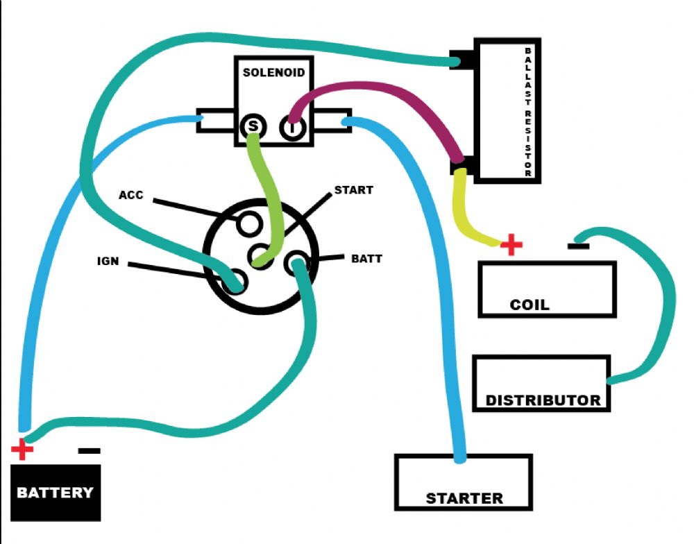
Install Ballast Resistor To Ignition System Traditionally, ignition systems didn’t use a ballast, meaning that the ignition system used a 12v coil with a 12v feed from the battery via the ignition switch. this system is fine when the engine is running, however can be problematic when starting. because the starter motor draws a huge amount of current from the battery, the spark plugs. How to wire an ignition coil with a ballast resistorin this video, i will show you another way of wiring an ignition coil with a ballast resistor. the engin. 4. attach the ballast resistor to the firewall using the clamps. 5. connect the positive wire from the ignition to the positive end of the resistor. 6. connect the other terminal of the resistor to the positive terminal of the coil. 7. install the condenser, located with the ballast resistor on the firewall. 8. When wiring a ballast resistor to a 12v ignition coil, it is important to follow the manufacturer’s instructions carefully. in most cases, the ballast resistor should be wired in series with the positive terminal of the ignition coil. this will help regulate the voltage going to the coil and prevent overheating. 5) what are common symptoms.

Ballast Resistor 12 Volt Ignition Coil Wiring Diagram For Your Needs 4. attach the ballast resistor to the firewall using the clamps. 5. connect the positive wire from the ignition to the positive end of the resistor. 6. connect the other terminal of the resistor to the positive terminal of the coil. 7. install the condenser, located with the ballast resistor on the firewall. 8. When wiring a ballast resistor to a 12v ignition coil, it is important to follow the manufacturer’s instructions carefully. in most cases, the ballast resistor should be wired in series with the positive terminal of the ignition coil. this will help regulate the voltage going to the coil and prevent overheating. 5) what are common symptoms.

12v Ignition Coil Ballast Resistor Wiring Diagram Wiring Diagram

Comments are closed.