Water Level Sensor Arduino Circuit Diagram At Brian Rothman Blog

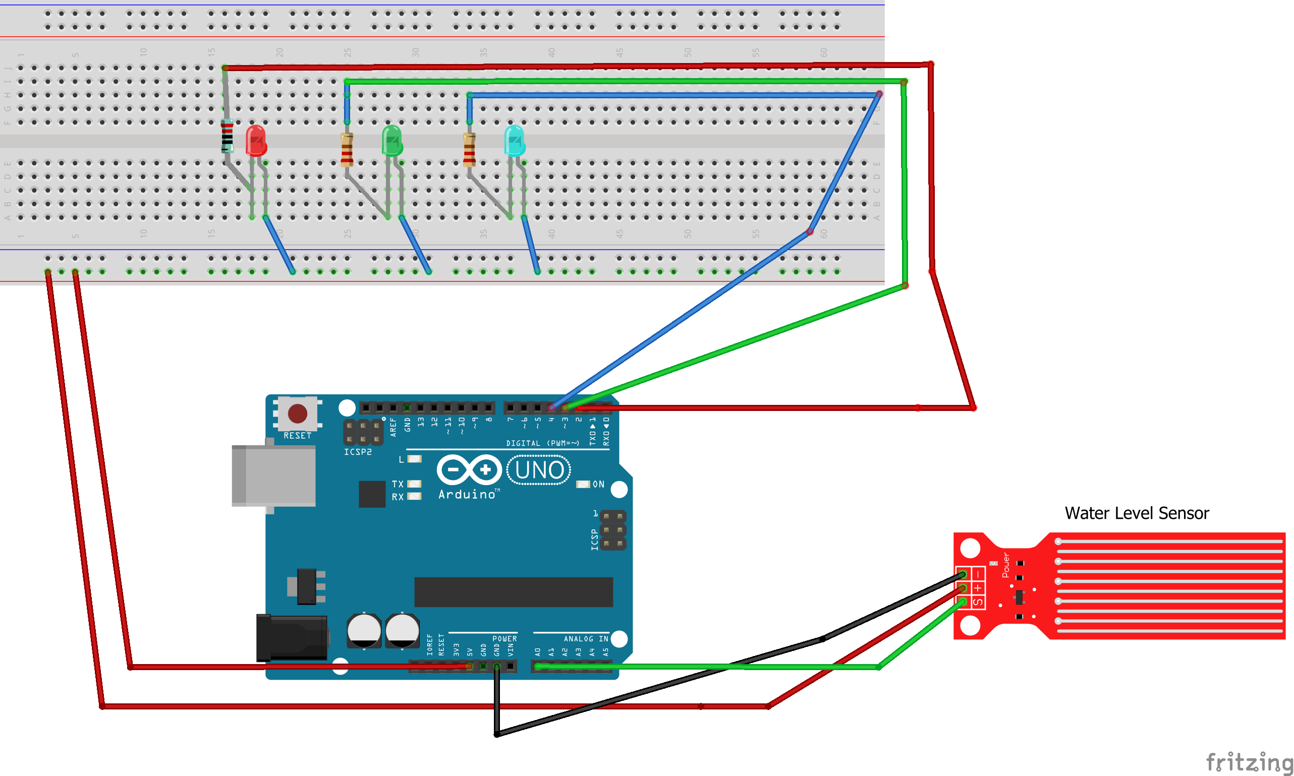
Water Level Sensor Arduino Circuit Diagram At Brian Rothman Blog Now we will add 3 leds showing 3 stages of the water level as low, medium, and high respectively. first lets discuss the circuit diagram. arduino water level sensor with 3 leds as output – circuit diagram. below you can see the circuit diagram of the water level sensor circuit along with three leds for showing the demonstration. Wiring a water level sensor to an arduino. let’s hook up the water level sensor to the arduino. to begin, connect the (vcc) pin on the module to 5v on the arduino and the – (gnd) pin to ground. one well known issue with these sensors is that they have a shorter lifespan because they are constantly exposed to moisture.

Water Level Sensor Arduino Circuit Diagram At Brian Rothman Blog Water level sensor pinout. the water level sensor has 3 pins: s (signal) pin: is an analog output that will be connected to one of the analog inputs on your arduino. (vcc) pin: supplies power for the sensor. it is recommended to power the sensor with between 3.3v – 5v. (gnd) pin: is a ground connection. ※ note that:. Serial.print("sensor = " ); serial.println(sensorvalue); first, the exact string “sensor=” is written in the serial window, followed by displaying the value of the sensorvalue variable, and then it goes to the next line. delay(1000);: the loop () commands are executed again, after a one second delay. 1. connect the water level sensor to arduino. these are the pins of the water level sensor and where they are connected to the arduino board. first, let's connect the water level sensor to the arduino. most water level sensors have three pins: vcc ( ), gnd ( ), and sig (signal). vcc ( ): connect this pin to the 5v pin on the arduino. Step 1: circuit diagram for interfacing water level sensor with arduino. in the diagram, we connect an led to the pwm pin 6 of the arduino board. the sensor's analog output pin connects to the a0 pin. the ground pin is shared between the module and the led, with vcc taken from the arduino's 5v pin. we'll program the arduino to adjust the led.

Comments are closed.