Thermo Electric Cooler Diagram

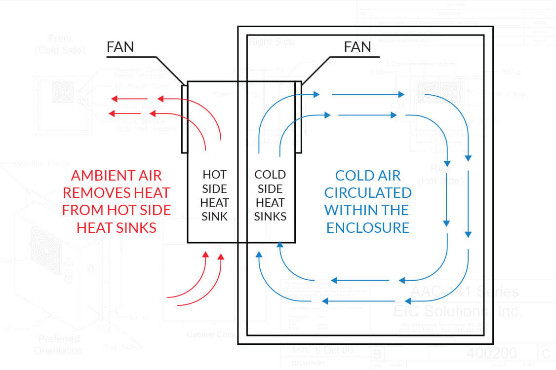
Thermoelectric Cooler Circuit Diagram Wiring Digital And Schematic Thermoelectric cooling uses the peltier effect to create a heat flux at the junction of two different types of materials. a peltier cooler, heater, or thermoelectric heat pump is a solid state active heat pump which transfers heat from one side of the device to the other, with consumption of electrical energy, depending on the direction of the current. 1.1 a thermoelectric (te) cooler, sometimes called a thermoelectric module or peltier cooler, is a semiconductor based electronic component that functions as a small heat pump. by applying a low voltage dc power source to a te module, heat will be moved through the module from one side to the other. one module face, therefore, will be cooled.

Thermoelectric Coolers Department Of Energy This video will show you how to use a w1209 digital thermostat to control everything and set the desired temperature on your peltier cooler.with a similar setup, you can expect a 10 15 celcius temperature difference between the diy cooler and ambient temperature. in fahrenheit, it went from 70 to 50 degrees. Use the function diagram for t h = 50°c to find the current to maintain Δt = 40°c, at the supplied voltage: from the diagram, i = 3.77 a. find the heat pumped from the function diagram, at i = 3.77 a and Δt = 40°c: from the diagram, q c = 20.75 w. thermal fatigue in peltier modules. thermoelectric coolers can be susceptible to thermal fatigue. With thermoelectric cooling, cooling and heating are performed with the same device by simply reversing the direction of electric current to the module. this can lead to reduced complexity and lower costs for some applications. 6. compact size – thermoelectric modules are very compact with simple geometry. Thermoelectric coolers (tecs) are solid state devices that pump heat. it generally requires a heat transfer mechanism such as a heat exchanger to absorb and dissipate heat. the device operates on dc voltage and when powering on the current flows through the thermoelectric cooler and carries electrons from one side of the ceramic to the other.

A Schematic Diagram Of A Thermoelectric Cooler Download Scientific With thermoelectric cooling, cooling and heating are performed with the same device by simply reversing the direction of electric current to the module. this can lead to reduced complexity and lower costs for some applications. 6. compact size – thermoelectric modules are very compact with simple geometry. Thermoelectric coolers (tecs) are solid state devices that pump heat. it generally requires a heat transfer mechanism such as a heat exchanger to absorb and dissipate heat. the device operates on dc voltage and when powering on the current flows through the thermoelectric cooler and carries electrons from one side of the ceramic to the other. Figure (2.2) schematic diagram of a typical thermoelectric cooler 2.2.1 both n type and p type bismuth telluride thermoelectric materials are used in a thermoelectric cooler. this arrangement causes heat to move through the cooler in one direction only while the electrical current moves back and forth alternately between the top and bottom. On demand mobile cpu cooling with thin film thermoelectric array. a, diagram of the tested mobile chip used in the simulation, along with the positions and names of each block 113. b , illustration of the chip temperature during the thermal analysis at various points of time 113 .

Schematic Diagram Of A Thermoelectric Cooler Download Scientific Diagram Figure (2.2) schematic diagram of a typical thermoelectric cooler 2.2.1 both n type and p type bismuth telluride thermoelectric materials are used in a thermoelectric cooler. this arrangement causes heat to move through the cooler in one direction only while the electrical current moves back and forth alternately between the top and bottom. On demand mobile cpu cooling with thin film thermoelectric array. a, diagram of the tested mobile chip used in the simulation, along with the positions and names of each block 113. b , illustration of the chip temperature during the thermal analysis at various points of time 113 .

Comments are closed.