The Difference Between Schematic And Pictorial Diagrams Explained

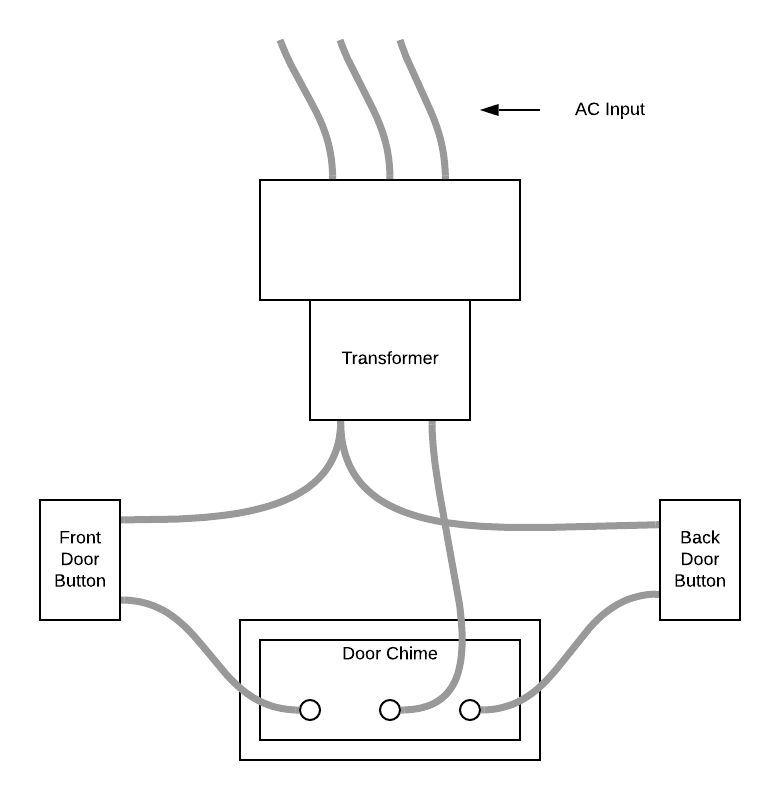
Explain The Difference Between A Pictorial Diagram And A Schematic Chemists use schematic drawings to describe how different elements interact with each other to create a product. pictorial diagrams, block diagrams, and wiring diagrams are the simplest diagrams and are best suited for the average homeowner or handyman tackling a weekend project. the diagrams include enough detail to identify components and to. In summary, while both schematic and pictorial diagrams serve the purpose of illustrating electrical circuits, they differ in their level of detail and complexity. schematic diagrams are more technical and precise, using symbols and lines to represent the components and connections. pictorial diagrams, on the other hand, provide a simplified.

Explain The Difference Between A Wiring Diagram And A Circuit Diagram Unlike a schematic diagram, however, it does not use symbols to represent the parts of the system. rather, it uses more detailed images that are exact representations of the parts. while pictorial diagrams are more readily understandable by those with no technical background, they are more difficult to create and require a greater level of. A schematic diagram is a visual representation of a system or process, using symbols, lines, and arrows to show the connections and flow of the various components or elements involved. it is a way to illustrate complex ideas or concepts in a concise and organized manner. using a schematic diagram, engineers, technicians, and other professionals. A power wiring diagram, also known as an electrical power distribution diagram, is a schematic representation of an electrical system that specifically focuses on illustrating the distribution of electrical power within a facility, a complex electrical network or specific electrical circuit. it typically shows the connections and routes of. A schematic, also known as a circuit diagram, is a visual representation of an electronic circuit. it uses standardized symbols to represent electronic components and shows how these components are connected to form a circuit. unlike a pictorial diagram, a schematic doesn’t aim to represent the physical layout of the components.

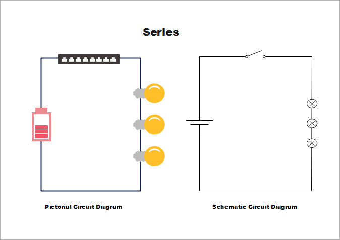
The Difference Between Schematic And Pictorial Diagrams Explained A power wiring diagram, also known as an electrical power distribution diagram, is a schematic representation of an electrical system that specifically focuses on illustrating the distribution of electrical power within a facility, a complex electrical network or specific electrical circuit. it typically shows the connections and routes of. A schematic, also known as a circuit diagram, is a visual representation of an electronic circuit. it uses standardized symbols to represent electronic components and shows how these components are connected to form a circuit. unlike a pictorial diagram, a schematic doesn’t aim to represent the physical layout of the components. Circuit diagram examples. example: three 5 v batteries are used to power a circuit containing three light bulbs. to represent the verbal description of the circuit, we can draw three light bulbs and connect them to three cells using wires. the circuit diagram assumes that the light bulbs are connected in series. The schematic diagram (figure 6.2.1 6.2. 1), often called a ladder diagram, is intended to be the simplest form of an electrical circuit. this diagram shows the circuit components on horizontal lines without regard to their physical location. it is used for troubleshooting because it is easy to understand the operation of the circuit.

Difference Between Schematics And Circuit Diagrams Edraw Circuit diagram examples. example: three 5 v batteries are used to power a circuit containing three light bulbs. to represent the verbal description of the circuit, we can draw three light bulbs and connect them to three cells using wires. the circuit diagram assumes that the light bulbs are connected in series. The schematic diagram (figure 6.2.1 6.2. 1), often called a ladder diagram, is intended to be the simplest form of an electrical circuit. this diagram shows the circuit components on horizontal lines without regard to their physical location. it is used for troubleshooting because it is easy to understand the operation of the circuit.

The Difference Between Schematic And Pictorial Diagrams Explained

Comments are closed.