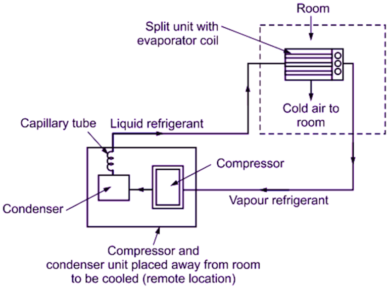
Split Air Conditioner Schematic Diagram

Refrigeration Schematic Diagram Of The Split Air Conditioning System Welcome to [wiring wonder]! in this video, we delve into the intricate world of split ac systems, breaking down the schematic wiring diagram step by step. wh. In this article, we’ll look at the schematic diagram of split type air conditioning to understand how it functions. split type air conditioners have two main components: an outdoor unit and an indoor unit. the outdoor unit houses the compressor, condenser, and expansion valve. the indoor unit contains a fan and evaporator coil.

What Is Split Air Conditioning System Working Construction The split unit air conditioning system diagram represents the mechanical and electrical components of a typical split air conditioning system. this type of air conditioning system is commonly used in residential and commercial buildings to provide cooling and ventilation. the diagram shows two main components: the indoor unit and the outdoor. The split type room air conditioner is comprised of two parts. 1) the outdoor unit, the outdoor unit, fitted outside the room, houses components like the compressor, condenser and expansion valve. 2) the indoor unit. the indoor unit comprises the evaporator or cooling coil and the cooling fan. the split air conditioner can be used to cool one. A schematic diagram is a representation of an electrical circuit using symbols to illustrate the connections and components. it shows how the various parts are interconnected and the flow of current within the system. schematic diagrams are often used to troubleshoot and understand the overall layout of complex systems, such as ac split system. A split system air conditioner is a type of air conditioning system that consists of two main components: an indoor unit and an outdoor unit. these units are connected by a refrigerant line, electrical wiring, and a drain pipe. the indoor unit is typically mounted on a wall or ceiling, while the outdoor unit is placed outside the building.

Schematic Diagram Of The Traditional Split Air Conditioner With The A schematic diagram is a representation of an electrical circuit using symbols to illustrate the connections and components. it shows how the various parts are interconnected and the flow of current within the system. schematic diagrams are often used to troubleshoot and understand the overall layout of complex systems, such as ac split system. A split system air conditioner is a type of air conditioning system that consists of two main components: an indoor unit and an outdoor unit. these units are connected by a refrigerant line, electrical wiring, and a drain pipe. the indoor unit is typically mounted on a wall or ceiling, while the outdoor unit is placed outside the building. Run the control wires. match the color of the wires to the labeled numbers. most mini split units will have the inside and outside units marked with numbers 1, 2, 3, and ground which the wires color code will match. for example, if a red wire is connected to the inside number 1, it will be connected outside to the number labeled 1. Wiring diagram manual split system horizontal air conditioner 421 03 1600 00 3 specifications subject to change without notice. 345082−101 — (c,h,t)sa660gkb 345082 101 rev. a 1. compressor and fan motor furnished with inherent thermal protection. 2. to be wired in accordance with national electric code (n.e.c.) and local codes. 3.

Circuit Diagram Of Split Air Conditioner Run the control wires. match the color of the wires to the labeled numbers. most mini split units will have the inside and outside units marked with numbers 1, 2, 3, and ground which the wires color code will match. for example, if a red wire is connected to the inside number 1, it will be connected outside to the number labeled 1. Wiring diagram manual split system horizontal air conditioner 421 03 1600 00 3 specifications subject to change without notice. 345082−101 — (c,h,t)sa660gkb 345082 101 rev. a 1. compressor and fan motor furnished with inherent thermal protection. 2. to be wired in accordance with national electric code (n.e.c.) and local codes. 3.

Comments are closed.