Solved Q3 Determine The Equivalent Impedance Ofthe Chegg

Solved Q3 Determine The Equivalent Impedance Ofthe Chegg Determine the equivalent impedance ofthe following network. 42 eq your solution’s ready to go! our expert help has broken down your problem into an easy to learn solution you can count on. Question: qdetermine the equivalent impedance of the circuit shown in figure q3 in phasor formlooking into its open terminals for ω=100rads.q for the circuit shown in figure q8, using the real diode model with a von =0.7v, find thevalues of i and v .qfind the vahe of r in the circuit shown in figure q11, given vi= 0.5v,k=0.2mav2q for the circuit shown in.

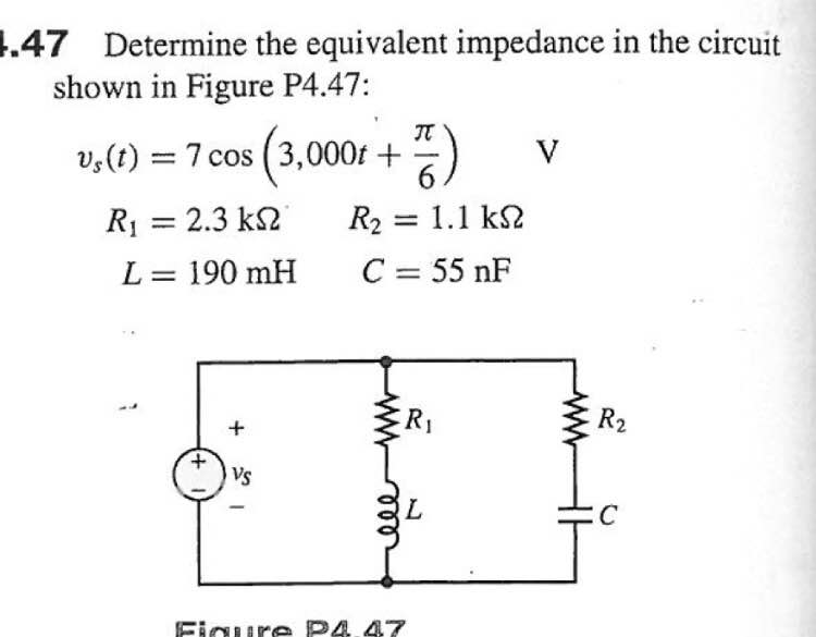
Solved Determine The Equivalent Impedance In The Circuit Chegg Question: determine the equivalent impedance of the circuit shown in figure 1 when the circuit operates at ω 100 rad s. (30 points) 10 mf 5Ω 50 mh figure 1 find i1 (t), i2 (t), and vo (t) in the circuit of figure 2. (40 points) 10 mf i1 (t) vin)5cos (100t60°) 50 mh figure 2. here’s the best way to solve it. Here’s the best way to solve it. 3. for the ac network shown below in figures q3: (a) determine the equivalent impedance and equivalent voltage across a b both in polar and rectangular co ordinates by using millman's theorem for the circuit shown in figure q3a. given z1=2 j5; z=3 j4; z3=4 j5; z4=3 j5; e1=10 j0, ez=20 j0 and ex=10 j0. Question: problem 2. (5 points)determine the thevenin equivalent of the circuit seenfrom the terminals of zl. determine the impedance,zl, for maximum average power transfer and the valueof the maximum average power transferred to zl for theciruit shown givenis=3a?145@r=18Ωzl1=9iΩref: hayt, sect. 11.2the thevenin impedance of the circuit (not including(:zl. B) figure q3b shows a common gate amplifier with a resistive load rp. assuming that body effect, y # 0 and channel length modulation, i # 0, determine the input impedance rin and the equivalent transconductance gm. 17 marks vdd rd vout m • v6 rin rs vin 16 figure q3b b) based on figure q1(a), explain with equations the minimum and maximum allowable output voltage swing.

Comments are closed.