Solved Figure Below Shows The Continuous Cooling Chegg

Solved 5 Figure Below Shows The Continuous Cooling Chegg Question: figure below shows the continuous cooling transformation diagram for a 1.13 wt% c iron–carbon alloy. which of the following heat treatments will produce a microstructure of proeutectoid cementite, fine pearlite and martensite?. Here’s the best way to solve it. figure below shows the continuous cooling transformation diagram for a 1.13 wt% c iron carbon alloy. which of the following heat treatments will produce a microstructure of proeutectoid cementite, fine pearlite and martensite? 800 a c 600 temperature (°c) 400 200 0 0.1 (a) p a (b) a m 10 (c) 103 time (s) (d) 105.

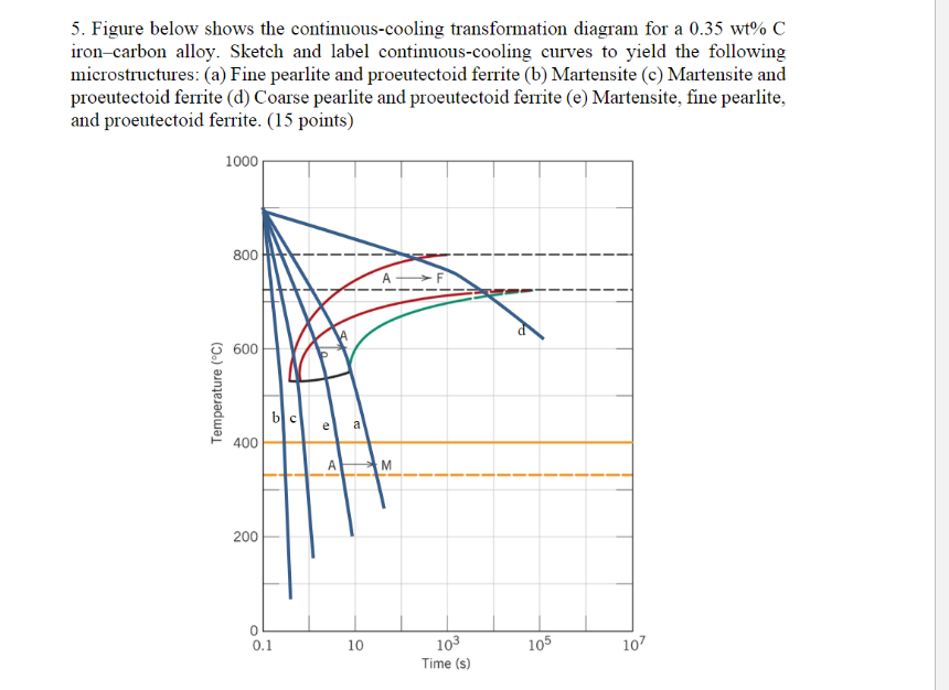
Solved I The Figure Shows The Continuous Cooling Chegg Definition: stability of phases during continuous cooling of austenite. there are two types of cct diagrams. i) plot of (for each type of transformation) transformation start, specific fraction of transformation and transformation finish temperature against transformation time on each cooling curve. Figure 10.40 shows the continuous cooling transformation diagram for a 0.35 wt\% $\mathrm{c}$ iron carbon alloy. make a copy of this figure and then sketch and label continuous cooling curves to yield the following microstructures: (a) fine pearlite and proeutectoid ferrite (b) martensite (c) martensite and proeutectoid ferrite (d) coarse pearlite and procutectoid ferrite (e) martensite, fine. Figure 11.51 shows the continuous cooling transformation diagram for a 0.35 wt% c iron– carbon alloy. make a copy of this figure, and then sketch and label continuous cooling curves to yield the following microstructures: (a) fine pearlite and proeutectoid ferrite (b) martensite (c) martensite and proeutectoid ferrite(d) coarse pearlite and proeutectoid ferrite (e) martensite, fine pearlite. Figure 10.40 shows the continuous cooling transformation diagram for a 1.13 wt% c iron carbon alloy. make a copy of this figure and then sketch and label continuous cooling curves to yield the following microstructures: (a) fine pearlite and proeutectoid cementite (b) martensite (c) martensite and proeutectoid cementite.

Solved Figure Below Shows The Continuous Cooling Chegg Figure 11.51 shows the continuous cooling transformation diagram for a 0.35 wt% c iron– carbon alloy. make a copy of this figure, and then sketch and label continuous cooling curves to yield the following microstructures: (a) fine pearlite and proeutectoid ferrite (b) martensite (c) martensite and proeutectoid ferrite(d) coarse pearlite and proeutectoid ferrite (e) martensite, fine pearlite. Figure 10.40 shows the continuous cooling transformation diagram for a 1.13 wt% c iron carbon alloy. make a copy of this figure and then sketch and label continuous cooling curves to yield the following microstructures: (a) fine pearlite and proeutectoid cementite (b) martensite (c) martensite and proeutectoid cementite. 1045 continuous aisi martensite pearlite6 continuous cooling transformation (cct) diagram for 100cr6 alloy solved 4. using the continuous cooling transformationcooling continuous mo. ttt diagrams: 1. the basic idea. check details. solved 5. figure below shows the continuous cooling. Here’s the best way to solve it. 5. figure below shows the continuous cooling transformation diagram for a 0.35 wt% c iron carbon alloy. make a copy of this figure, and then sketch and label continuous cooling curves to yield the following microstructures: (a) fine pearlite and proeutectoid ferrite (b) martensite (c) martensite and.

Comments are closed.