Solidworks Basics Of Reference Geometry Axis

Solidworks Basics Of Reference Geometry Axis The reference axis will be created coincident to the point and normal to the face or plane. in all scenarios, the reference axis will show up as a feature in your featuremanager design tree. i hope this gives you a better understanding of ways to create a reference geometry axis to make you more efficient in solidworks! nicole kelley. For basic solidworks models, users can often complete designs by leveraging only the default planes and available model geometry. however, as the complexity of designs increases, it often becomes necessary to create and utilize reference geometry to produce models with appropriate design intent. reference geometry includes planes, axes.

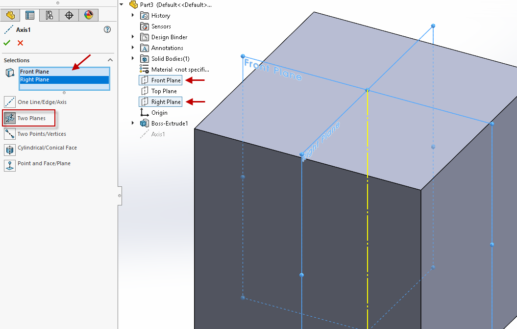
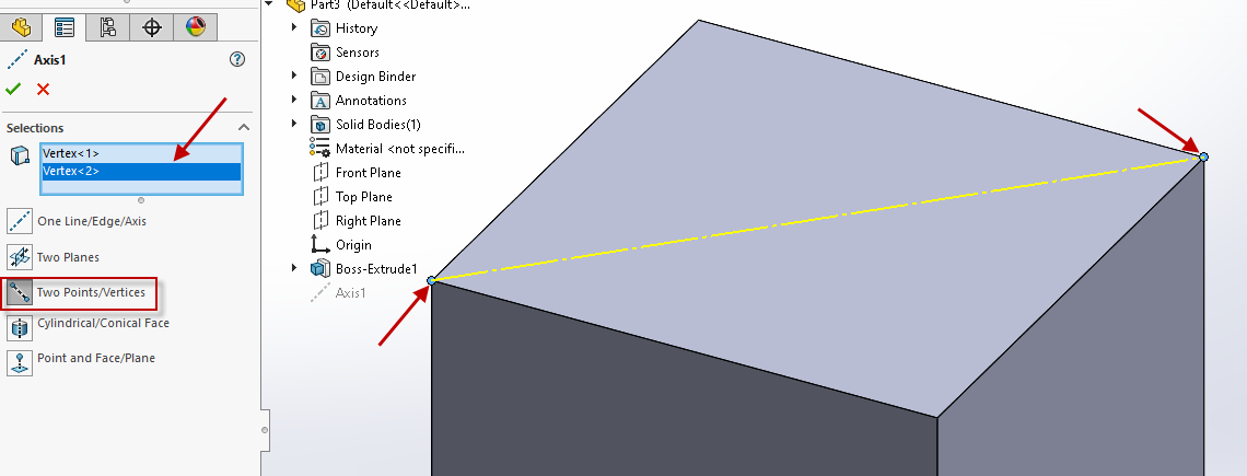
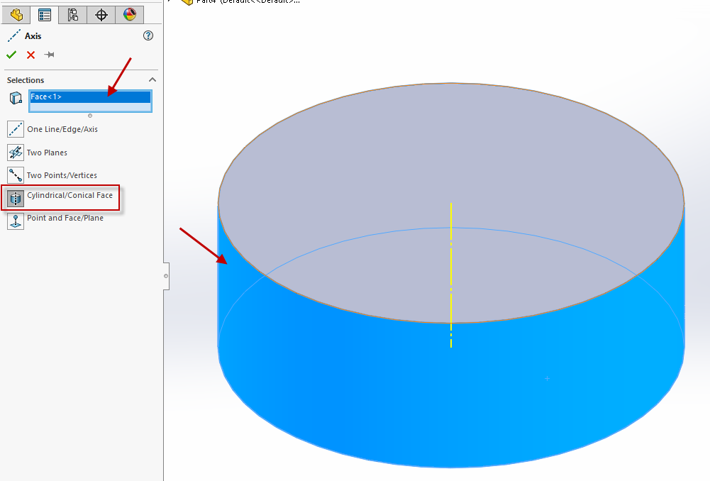
Solidworks Basics Of Reference Geometry Axis It will focus on what’s new in solidworks 2019. for basic solidworks models, users can often complete designs by leveraging only the default planes and available model geometry. however, as the complexity of designs increases, it often becomes necessary to create and utilize reference geometry to produce models with appropriate design intent. Reference geometry. reference geometry defines the shape or form of a surface or a solid. reference geometry includes items such as planes, axes, coordinate systems, and points. you can use reference geometry in the creation of several kinds of features. for example:. To create a reference axis: click axis on the reference geometry toolbar, or click insert > reference geometry > axis. select the axis type in the axis propertymanager, then select the required entities for that type. verify that the items listed in reference entities correspond to your selections. click . The selected face of the cylindrical hole can rotate about or move along the reference axis shown in the figure. thick red arrows represent allowable motions. fig. 1 fig. 2 fig. 3 consider fitting the ring in fig. (1) inside the ring in fig. (2). the inner ring (fig. 1) has an outer diameter of 18.2 cm and is made of an elastic material.

Solidworks Basics Of Reference Geometry Axis To create a reference axis: click axis on the reference geometry toolbar, or click insert > reference geometry > axis. select the axis type in the axis propertymanager, then select the required entities for that type. verify that the items listed in reference entities correspond to your selections. click . The selected face of the cylindrical hole can rotate about or move along the reference axis shown in the figure. thick red arrows represent allowable motions. fig. 1 fig. 2 fig. 3 consider fitting the ring in fig. (1) inside the ring in fig. (2). the inner ring (fig. 1) has an outer diameter of 18.2 cm and is made of an elastic material. Learn about five different options on how to create a reference geometry axis in solidworks. Creating new planes (page 6 4) if we need to create a new reference plane, we invoke the reference geometry tool in the features commandmanager and select the plane option from the flyout (figure 6 4, page 6 3) once the plane option is selected, the plane propertymanager will be displayed (figure 6 5, page 6 4 and to the left).

Solidworks Basics Of Reference Geometry Axis Learn about five different options on how to create a reference geometry axis in solidworks. Creating new planes (page 6 4) if we need to create a new reference plane, we invoke the reference geometry tool in the features commandmanager and select the plane option from the flyout (figure 6 4, page 6 3) once the plane option is selected, the plane propertymanager will be displayed (figure 6 5, page 6 4 and to the left).

Comments are closed.