Rl Series Circuit Phasor Diagram

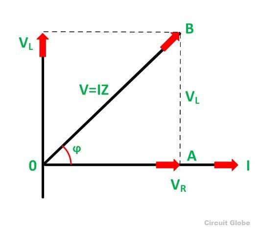
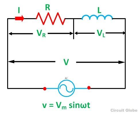
What Is Rl Series Circuit Phasor Diagram Power Curve Circuit Globe Rl circuit for drawing the phasor diagram of series rl circuit; follow the following steps: step i. in case of series rl circuit, resistor and inductor are connected in series, so current flowing in both the elements are same i.e i r = i l = i. so, take current phasor as reference and draw it on horizontal axis as shown in diagram. step ii. Learn how to calculate the impedance, phase angle, current, and power in an rl series circuit with a resistor and an inductor. see the phasor diagram, impedance triangle, and power triangle for the circuit and examples.

Rl Series Circuit Analysis Phasor Diagram Examples Derivation Learn how to analyze an rl series circuit with an inductor and a resistor connected in series across an ac source. see the phasor diagram, the voltage equation, the impedance, the current, the power factor and the power in the circuit. Learn how to draw the phasor diagram of an rl series circuit and understand the phase angle, impedance and power factor. see the waveform and power curve of the rl series circuit and how it differs from the resistive circuit. In an rl series circuit, which consists of a resistor (r) and an inductor (l) connected in series, a phasor diagram is a graphical representation used to understand the behavior and relationships between current, voltage, and phase shift in the circuit. when an alternating current (ac) is applied to the rl series circuit, the voltage across the. Figure (2): rl series circuit phasor diagram. the phasor diagram is drawn by taking the current ‘i’ as reference phasor as shown in figure (2). the voltage drop ‘v r ‘ is in phase with current i since r is a pure resistance and voltage drop ‘v l ‘ leads current ‘i’ by 90º since l is a pure inductance. from the phasor diagram.

Rl Circuit Working Phasor Diagram Impedance Its Uses In an rl series circuit, which consists of a resistor (r) and an inductor (l) connected in series, a phasor diagram is a graphical representation used to understand the behavior and relationships between current, voltage, and phase shift in the circuit. when an alternating current (ac) is applied to the rl series circuit, the voltage across the. Figure (2): rl series circuit phasor diagram. the phasor diagram is drawn by taking the current ‘i’ as reference phasor as shown in figure (2). the voltage drop ‘v r ‘ is in phase with current i since r is a pure resistance and voltage drop ‘v l ‘ leads current ‘i’ by 90º since l is a pure inductance. from the phasor diagram. An rl series circuit (also known as an rl filter or rl network) is an electrical circuit consisting of a resistor r and an inductor l connected in series, driven by a voltage source or current source. the impedance z˙r of the resistor r and the impedance z˙l of the inductor l can be expressed by the following equations: z˙r z˙l = = r jxl. In a series connected rl circuit, the current lags the inductor voltage (v l) by 90 and lags the supply voltage (e) by an angle less than 90°. image used courtesy of amna ahmad . phasor diagram. the phasor diagram for the series rl circuit is drawn by starting with the current phasor because the current is the common quantity in a series circuit.

Phasor Diagram Of Rl Circuit Solved V Figure 7 7 Phasor Diagrams An rl series circuit (also known as an rl filter or rl network) is an electrical circuit consisting of a resistor r and an inductor l connected in series, driven by a voltage source or current source. the impedance z˙r of the resistor r and the impedance z˙l of the inductor l can be expressed by the following equations: z˙r z˙l = = r jxl. In a series connected rl circuit, the current lags the inductor voltage (v l) by 90 and lags the supply voltage (e) by an angle less than 90°. image used courtesy of amna ahmad . phasor diagram. the phasor diagram for the series rl circuit is drawn by starting with the current phasor because the current is the common quantity in a series circuit.

Comments are closed.