Pto Hyd Cooler Relay Wiring Diagram

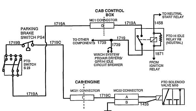
How To Wire A Pto Switch When using a direct mount method, in pto installation, use a support bracket to support the pump to the transmission when the following conditions apply: the pump weight 40 pounds or more; the combined length of the pto and pump reaches or exceeds 18 inches from the pto centerline to the end of the pump. The wiring diagram is a visual representation of the electrical connections and components involved in the pto system. it shows how power is transmitted from the engine to the pto, and how it is distributed to the different attachments. there are several types of pto wiring diagrams, depending on the make and model of the vehicle or equipment.

Pto Wiring Diagram A power take off (pto) switch is an essential component in the wiring system of various vehicles and machinery, particularly those equipped with power take off systems. a power take off system allows the transfer of power from the engine of a vehicle or machine to an attached implement or accessory, such as a hydraulic pump or a winch. the pto. Our model 934 thermaflow system.the thermaflow assembly is designed to cool and filter the oil required. operate your hydraulic system. the oil is cooled by forcing air across co. ing fins on the heat exchanger. this system utilizes either an electric or hydraulic fan mo. r to force air across the fins. the fan motor options and control v. lve. Remember to attach all warning decals and labels to the visor and dash. good solid crimps are important. check to make sure you have good secure crimps. it takes 20 pounds to pull off a good crimp for 18 gage wire. soldering is the prefer method. twisting wires together and black tape is never recommended. The 2" × 3" pto equipped caution label is to be placed within the cab of the vehicle and in easy view of the vehicle operator. it should be located . near the pto control, when the control is installed in the vehicle dash. see figure 2. this label directs the operator to read the pto operating instructions on the “visor label”.

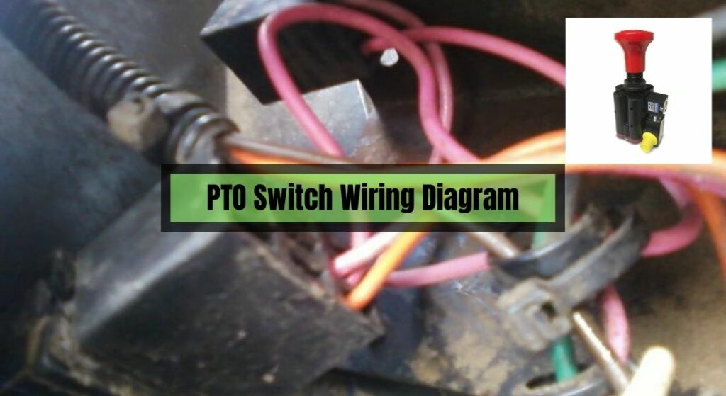
The Guide On Pto Switch Wiring Diagram Lawnask Remember to attach all warning decals and labels to the visor and dash. good solid crimps are important. check to make sure you have good secure crimps. it takes 20 pounds to pull off a good crimp for 18 gage wire. soldering is the prefer method. twisting wires together and black tape is never recommended. The 2" × 3" pto equipped caution label is to be placed within the cab of the vehicle and in easy view of the vehicle operator. it should be located . near the pto control, when the control is installed in the vehicle dash. see figure 2. this label directs the operator to read the pto operating instructions on the “visor label”. The diagram will indicate which wires need to be connected to the switch terminals. 4. prepare the wires: using wire strippers, carefully remove the insulation from the ends of the wires that need to be connected to the switch. ensure that there is enough bare wire exposed to make a secure connection. 5. Follow installation instructions for fr series pto in03 01 until step 41. locate a 12v dc source in under the dash and connect the fused red wire. locate a battery ground and attach the black wire with the ring terminal to the ground.

Comments are closed.