Phasor Diagram Of Rl Rc Rlc Circuit

Phasor Diagram Of Rl Rc And Rlc Circuits With Examples Youtube Let us calculate the time taken for our capacitor to charge up in the circuit. Ƭ = rc = (1000 * (470*10^ 6)) = 0.47 seconds t = 5Ƭ = (5 * 0.47) t = 2.35 seconds. we have calculated that the time taken for the capacitor to charge up will be 2.35 seconds, the same can also be verified from the graph above. Since the value of frequency and inductor are known, so firstly calculate the value of inductive reactance x l: x l = 2πfl ohms. step 2. from the value of x l and r, calculate the total impedance of the circuit which is given by. step 3. calculate the total phase angle for the circuit θ = tan – 1 (x l r). step 4.

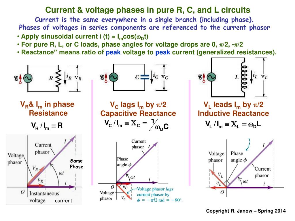
Phasor Diagram Of Rl Rc Rlc Circuit To draw the phasor diagram of rl series circuit, the current i (rms value) is taken as reference vector because it is common to both elements. voltage drop v r is in phase with current vector, whereas, the voltage drop in inductive reactance v l leads the current vector by 90 o since current lags behind the voltage by 90 o in the purely inductive circuit. In this video, phasor diagram representation of voltage and current for series rc, rl and rlc circuit has been explained and the examples based on this phaso. Series rlc circuit example no1. a series rlc circuit containing a resistance of 12Ω, an inductance of 0.15h and a capacitor of 100uf are connected in series across a 100v, 50hz supply. calculate the total circuit impedance, the circuits current, power factor and draw the voltage phasor diagram. inductive reactance, xl. capacitive reactance, xc. For drawing the phasor diagram of series rlc circuit, follow these steps: step – i. in case of series rlc circuit; resistor, capacitor and inductor are connected in series; so, the current flowing in all the elements are same i.e i r = i l = i c = i. for drawing the phasor diagram, take current phasor as reference and draw it on horizontal.

Phasor Diagram Of Rl Rc Rlc Circuit Series rlc circuit example no1. a series rlc circuit containing a resistance of 12Ω, an inductance of 0.15h and a capacitor of 100uf are connected in series across a 100v, 50hz supply. calculate the total circuit impedance, the circuits current, power factor and draw the voltage phasor diagram. inductive reactance, xl. capacitive reactance, xc. For drawing the phasor diagram of series rlc circuit, follow these steps: step – i. in case of series rlc circuit; resistor, capacitor and inductor are connected in series; so, the current flowing in all the elements are same i.e i r = i l = i c = i. for drawing the phasor diagram, take current phasor as reference and draw it on horizontal. Phasors may be used to analyze the behavior of electrical and mechanical systems that have reached a kind of equilibrium called sinusoidal steady state. in the sinusoidal steady state, every voltage and current (or force and velocity) in a system is sinusoidal with angular frequency ω. however, the amplitudes and phases of these sinusoidal. Figure 3 rl series circuit impedance triangle. impedance calculation in rl series circuit example 1. problem: an ac series rl circuit is made up of a resistor that has a resistance value of 150 Ω and an inductor that has an inductive reactance value of 100 Ω. calculate the impedance and the phase angle theta (θ) of the circuit.

Comments are closed.