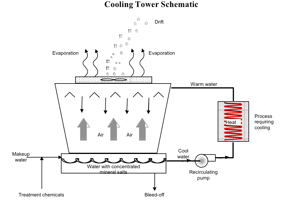
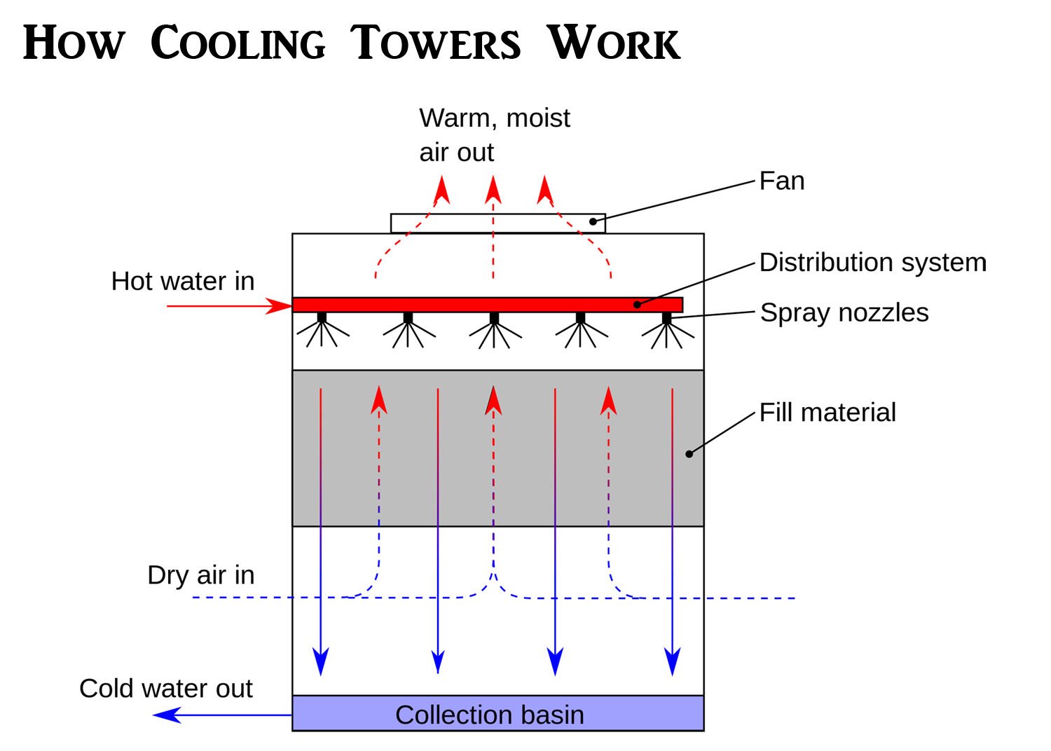
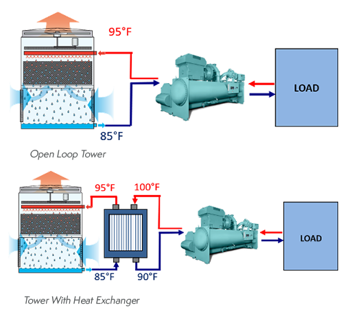
Open Loop Cooling Tower Schematic

Open Loop Cooling Tower The air drawn through this cascading water provides evaporative cooling similar to an open cooling tower, except that the cooled water never makes direct contact with the air. closed circuit cooling towers require much more energy to achieve the same cooling as an open circuit cooling tower. different types of closed circuit cooling tower systems. Condenser water return pipework [1] the cooling tower return pipework is installed to transport the warm water from the condenser side of the water cooled chiller to the cooling tower, with the flow being provided by the condenser water pumps that are installed on the supply side of the tower [tower to chiller] to move the water around the system.

Open Loop Cooling Tower Schematic Closed loop vs open loop operation. in a closed circuit cooling tower, the process fluid, which could be water, or a water glycol mixture is circulated within a closed loop piping system. there are two separate water sources, one external within a closed loop, and the second one that circulates water from the tower basin over the heat exchanger. In open loop and closed loop cooling towers, the fill media facilitates the contact between air and the water surface. this media helps the water spread into thin, flowing layers, maximizing the surface area exposed to the air flow. fill media is typically made from materials such as polypropylene, wood, or pvc. Operationally, closed cooling towers maintain their efficiency better than open towers with plate and frame heat exchangers simply because their heat transfer capability is far less impaired by surface fouling. that’s a brief overview of the differences between open and closed cooling towers that an engineer should consider in the earliest. The cooling tower circuit differs slightly from the basic “open” circuit in that the discharge piping is connected directly to a distribution basin. some towers are furnished with a distribution manifold with nozzles which require additional pressure. figure 3 typical “open” tower piping.

Open Loop Cooling Tower Schematic Operationally, closed cooling towers maintain their efficiency better than open towers with plate and frame heat exchangers simply because their heat transfer capability is far less impaired by surface fouling. that’s a brief overview of the differences between open and closed cooling towers that an engineer should consider in the earliest. The cooling tower circuit differs slightly from the basic “open” circuit in that the discharge piping is connected directly to a distribution basin. some towers are furnished with a distribution manifold with nozzles which require additional pressure. figure 3 typical “open” tower piping. Evaporative cooling towers exploit a simple and natural physical principle: forced evaporation of a minimal water quantity lowers the temperature of the main. Cooling towers work by using air to cool a working fluid (water). open loop cooling tower diagram. there are primarily three different methods in which a cooling tower can remove heat from water: 1. direct cooling – open loop. open loop cooling towers work by bringing the working fluid water into direct contact with the air.

Comments are closed.