Loop Diagram Electrical Circuits Theory

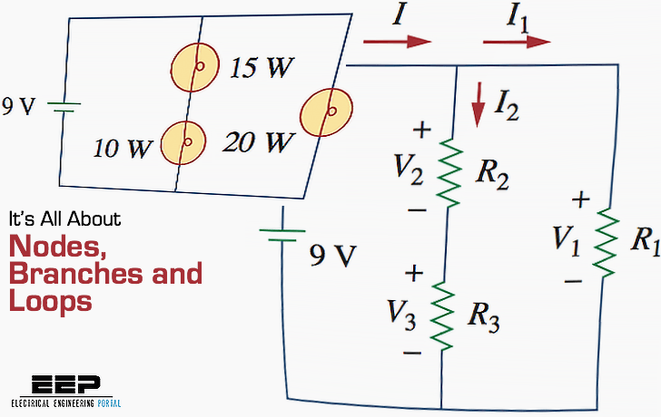
Loop Diagram Electrical Circuits Theory Node in electrical circuit: a node is a point in an electrical circuit where two or more circuit elements are connected, serving as a junction point. branch definition: a branch is the part of the circuit between two nodes that can deliver or absorb energy, excluding short circuits. loop definition: a loop is a closed path in the circuit where. Loops . a loop is any closed path in a circuit. a loop is a closed path formed by starting at a node, passing through a set of nodes, and returning to the starting node without passing through any node more than once. a loop is said to be independent if it contains at least one branch which is not a part of any other independent loop.
Loop Diagram Electrical Circuits Theory The circuit has 3 branches, 2 nodes (a and b) and 2 independent loops. using kirchhoffs current law, kcl the equations are given as: at node a : i1 i2 = i3. at node b : i3 = i1 i2. using kirchhoffs voltage law, kvl the equations are given as: loop 1 is given as : 10 = r1 i1 r3 i3 = 10i1 40i3. The mesh current method is a network analysis technique in which mesh (or loop) currents are assigned arbitrarily, and then kirchhoff’s voltage law and ohm’s law are applied systematically to solve for all unknown currents and voltages. step 1: identify and label the current loops. step 2: label the voltage drop polarities. A loop is a closed path formed by starting at a node, passing through a. set of nodes, and returning to the starting node without passing through. any node more than once. figure. 3 (representation of loop in the circuit) for example, as shown in figure.3, the circuit contains three loops. the first is loop a b d a, the second loop is b c d b. Kirchhoff's circuit laws. kirchhoff's circuit laws are two equalities that deal with the current and potential difference (commonly known as voltage) in the lumped element model of electrical circuits. they were first described in 1845 by german physicist gustav kirchhoff. [1] this generalized the work of georg ohm and preceded the work of.

Comments are closed.