Lcd With Arduino Proteus Simulation Proteus Tutorial Easy For All

Arduino To 16 2 Lcd Display Proteus Arduino Proteus Simulation In this video you will learn how to simulate lcd with arduino using proteus software .lcd with arduino proteus simulation || proteus tutorial easy for all. This commands in arduino can be provided using the codes. lcd stands for liquid crystal display. 16×2 lcd is named so because; it has 16 columns and 2 rows. there are a lot of combinations available like 8×1, 8×2, 10×2, 16×1, etc. but the most used one is the 16×2 lcd. so, it will have 16×2 = 32 characters in total and each character.

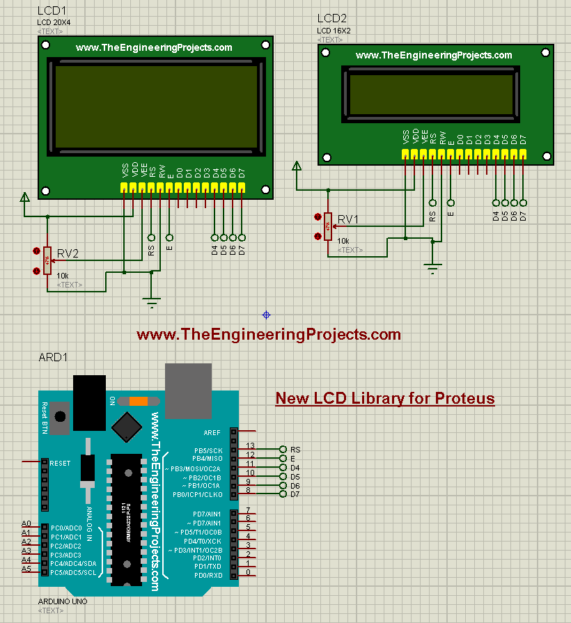
New Lcd Library For Proteus The Engineering Projects Step 1 download lcd library for proteus. first of all download the lcd library for proteus. simply search for the lcd library in your web browser and look for the library. simply download the library, unzip it and copy paste it in the proteus as we did in the case when installing the arduino library. this step is very simple. The correct way to simulate it btw is to add a pcf 8574 beween your arduino and the lcd. pins 4,5,6 of the 8574 go to rs, rw, e of the lcd, while p4 to p7 connect to the lcd d4 to d7. a0, a1, a2 in my case are grounded (this give address 0x20 in sim not in real life) the i2c address of the 8574 on proteus is 0x20. 1. download all library related files from github. download the zip file. 2. extract the zip file and navigate to proteus master\arduino\library. 3. copy both of the files and paste them in one of the following paths: c:\program files\labcenter electronics\proteus 8 professional\library. or. Step 2 – create new proteus project. next, we’ll create a blank proteus project and workspace to design our led blinking circuit: open proteus and click the new project icon, or use the menu file > new…. in the new project wizard dialog: enter a name like "arduinoled". select directory folder to store .pdsprj file.

Lcd With Arduino Proteus Simulation Proteus Tutorial Easy For All 1. download all library related files from github. download the zip file. 2. extract the zip file and navigate to proteus master\arduino\library. 3. copy both of the files and paste them in one of the following paths: c:\program files\labcenter electronics\proteus 8 professional\library. or. Step 2 – create new proteus project. next, we’ll create a blank proteus project and workspace to design our led blinking circuit: open proteus and click the new project icon, or use the menu file > new…. in the new project wizard dialog: enter a name like "arduinoled". select directory folder to store .pdsprj file. 16×2 lcd pinout: 16×2 lcd has a total of 16 pins. pin number1 is the ground and will be connected with the arduino’s ground. pin number 2 is the vdd and will be connected with the arduino’s 5 volts. pin number 3 the contrast pin, this pin will be connected with the potentiometer. the lcd contrast can be then controlled using a. In a previous tutorial, we discussed how to use tinkercad for simulating arduino projects and we’ve created some sample projects for testing.however, proteus isis is another simulation tool that is considered to be a more powerful software for electronic circuit simulation and especially microcontroller based applications.

Comments are closed.