Lcd Wiring Arduino Uno

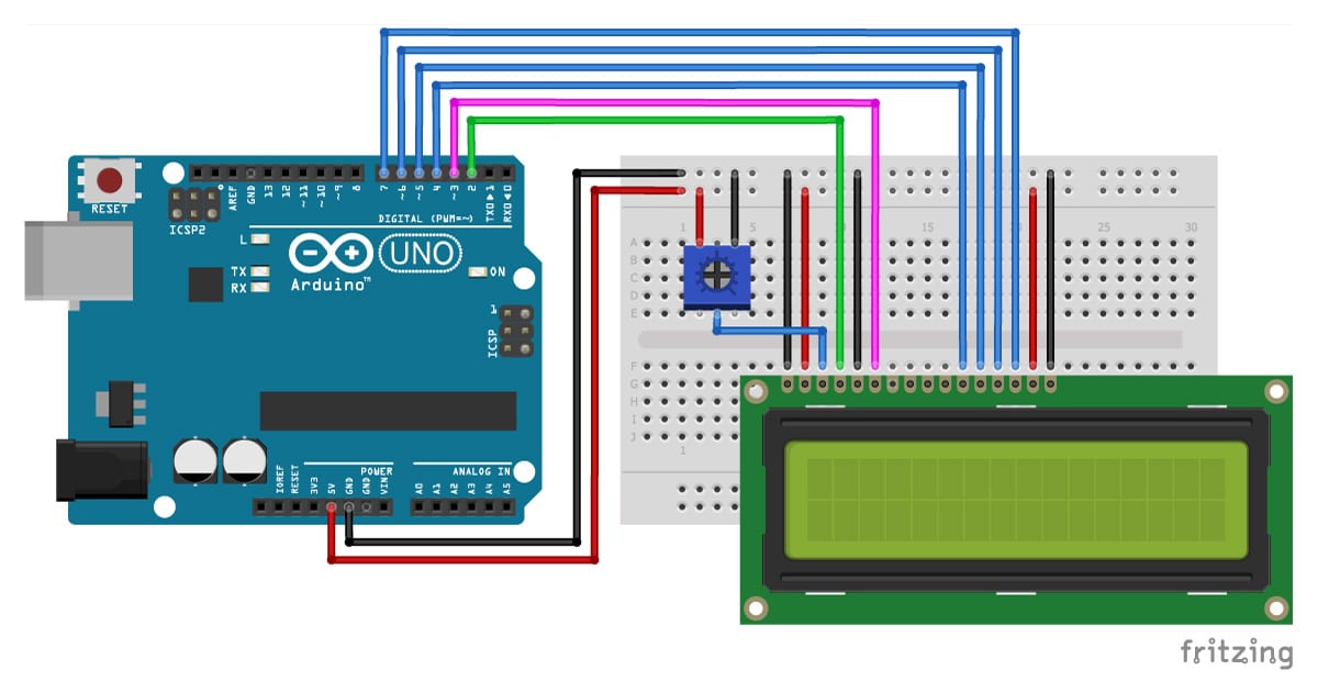
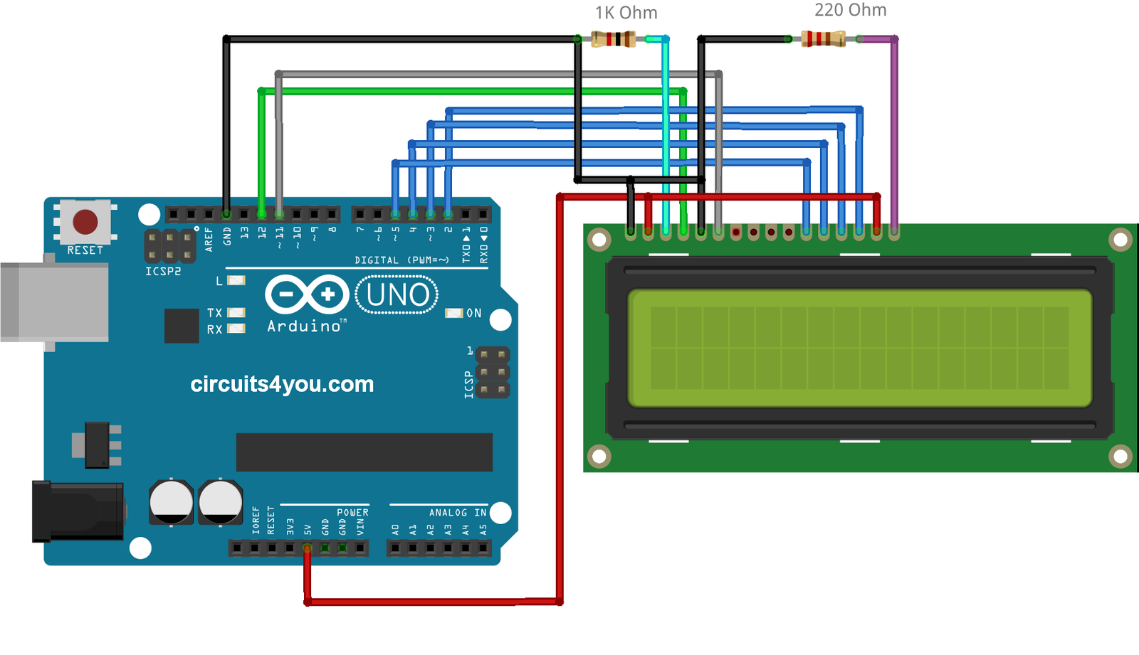
How To Control An Lcd Display With Arduino 8 Examples Before wiring the lcd screen to your arduino board we suggest to solder a pin header strip to the 14 (or 16) pin count connector of the lcd screen, as you can see in the image further up. to wire your lcd screen to your board, connect the following pins: lcd rs pin to digital pin 12; lcd enable pin to digital pin 11; lcd d4 pin to digital pin 5. Here’s how we need to connect the 16×2 lcd display to an arduino board. we will use just 6 digital input pins from the arduino board. the lcd’s registers from d4 to d7 will be connected to arduino’s digital pins from 4 to 7. the enable pin will be connected to pin number 2 and the rs pin will be connected to pin number 1.

16г 2 Lcd Interface With Arduino Uno Circuits4you Arduino lcd. in this arduino lcd tutorial, we will learn how to connect an lcd (liquid crystal display) to the arduino board. lcds are very popular and widely used in electronics projects for displaying information. there are many types of lcd. this tutorial takes lcd 16x2 (16 columns and 2 rows) as an example. Plug in the usb connector of the arduino to power the lcd. you should see the backlight light up. now rotate the potentiometer until one (16×2 lcd) or 2 rows (20×4 lcd) of rectangles appear. rotate the potentiometer until you see a row of rectangles appear. you can tweak the contrast later if needed. For this, do the connections as shown in the diagram above. connect pin 15 on the lcd to arduino's 5v pin. next, connect pin 16 on the lcd to the arduino's gnd pin. these pins are used to power the lcd's backlight. next, you need to set up the logic for the lcd. Connecting an lcd to an arduino. for these simple lcds to work, you only have to connect the register select, enable, and four data lines to the arduino. the contrast control pin should be connected to a potentiometer to allow the users to adjust the contrast of the display: if your display has a backlight, connect its anode and cathode to a.

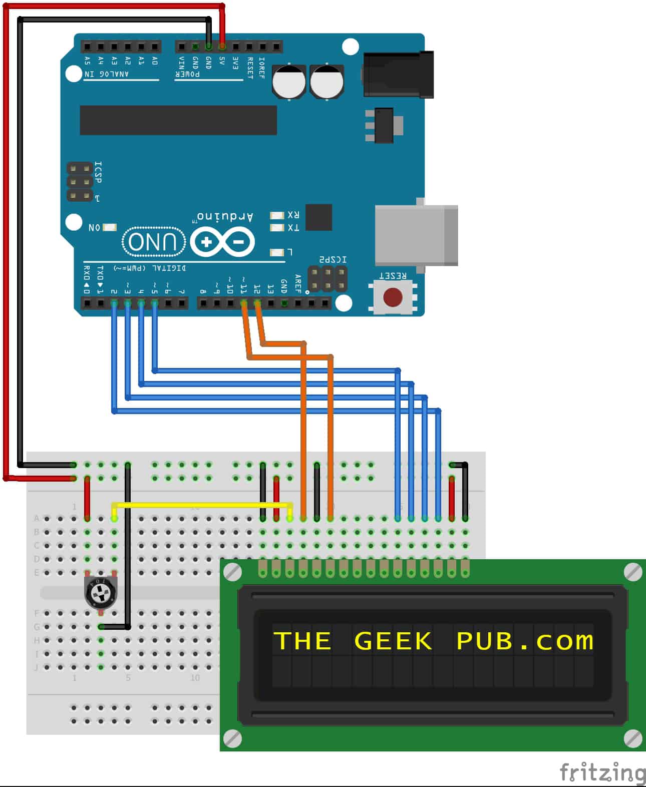
Arduino Lcd Display Wiring The Geek Pub For this, do the connections as shown in the diagram above. connect pin 15 on the lcd to arduino's 5v pin. next, connect pin 16 on the lcd to the arduino's gnd pin. these pins are used to power the lcd's backlight. next, you need to set up the logic for the lcd. Connecting an lcd to an arduino. for these simple lcds to work, you only have to connect the register select, enable, and four data lines to the arduino. the contrast control pin should be connected to a potentiometer to allow the users to adjust the contrast of the display: if your display has a backlight, connect its anode and cathode to a. The first step is to find a working library of them. i use liquid crystal i2c, and wire. link for liquid crystal here , link for wire here. the second step is to add the libraries to your arduino ide, to do that you go to sketch > include library > add zip library then find it in files. if it works, you should get a message saying it worked. In the previous tutorial, we had learned how to use the normal lcd. however, wiring between arduino and the normal lcd is complicated. therefore, lcd i2c has been created to simplify the wiring. actually, lcd i2c is composed of a normal lcd, an i2c module and a potentiometer. pinout. lcd i2c uses i2c interface, so it has 4 pins:.

Comments are closed.