Lcd 16×2 Display Interfacing With Arduino Uno Circuit Diagram Arduino

Lcd Display Arduino Circuit Diagram Pin headers to solder to the lcd display pins; 10k ohm potentiometer; 220 ohm resistor; hook up wires; breadboard; circuit. note that this circuit was originally designed for the arduino uno. as the arduino is communicating with the display using spi, pin 11 & 12 will change depending on what board you are using. for example, on a mkr wifi 1010. Hardware: arduino uno, power supply (5v), jhd 162alcd(16x2lcd), 100uf capacitor. software: arduino ide (arduino nightly). circuit diagram and explanation. in 16x2 lcd there are 16 pins over all if there is a back light, if there is no back light there will be 14 pins. one can power or leave the back light pins.

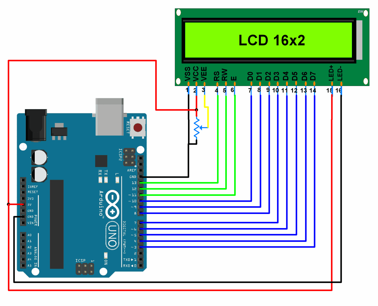
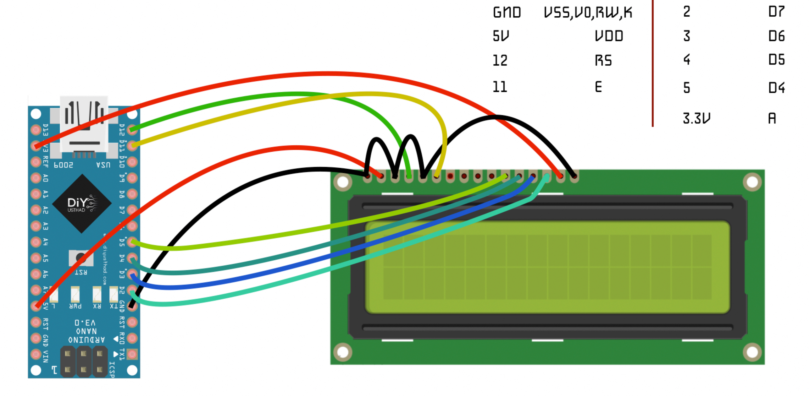
16x2 Lcd Pinout Diagram Interfacing 16x2 Lcd With Arduino 16x2 lcd module pinout. the 16x2 has a 16 pin connector. the module can be used either in 4 bit mode or in 8 bit mode. in 4 bit mode, 4 of the data pins are not used and in 8 bit mode, all the pins are used. and the connections are as follows: and here are the pins and corresponding functions. ground ground (0v). As shown in the above circuit diagram, this circuit will display “bilal malik” in the first row of lcd and “microcontrollers” in the second row of lcd. it is also shown in the above diagram, pin number 9 12 of arduino uno r3 is connected with lcd. you just have to write these pin numbers in lcd library functions arguments which tell arduino that which pin of arduino is connected with. In the setup, two functions are called. the first function is begin(). it is used to initialize the interface to the lcd screen and to specify the dimensions (columns and rows) of the display. if you’re using a 16×2 character lcd, you should pass 16 and 2; if you’re using a 20×4 lcd, you should pass 20 and 4. For more information about lcd 16x2 and how to use it, refer the topic lcd 16x2 module in the sensors and modules section. connection diagram of lcd16x2 with arduino interfacing 16x2 lcd with arduino uno . custom characters and regular characters on lcd 16x2 using arduino. displaying data on 16x2 lcd (custom characters as well as regular.

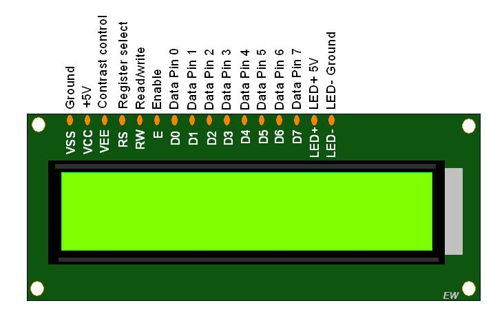
Lcd 16x2 Pinout In the setup, two functions are called. the first function is begin(). it is used to initialize the interface to the lcd screen and to specify the dimensions (columns and rows) of the display. if you’re using a 16×2 character lcd, you should pass 16 and 2; if you’re using a 20×4 lcd, you should pass 20 and 4. For more information about lcd 16x2 and how to use it, refer the topic lcd 16x2 module in the sensors and modules section. connection diagram of lcd16x2 with arduino interfacing 16x2 lcd with arduino uno . custom characters and regular characters on lcd 16x2 using arduino. displaying data on 16x2 lcd (custom characters as well as regular. In the interfacing diagram, we can see an arduino uno is connected to a 16×2 lcd using a breadboard. a 10k pot is also connected to control voltage at vo (contrast pin). here we will learn about arduino code which will be burned on arduino controller to run 16×2 lcd in 8 bit mode. in this mode all the data lines will be used for communications. 16x2 lcd pinout diagram. in this picture down below you will see a 16x2 lcd pinout diagram and the pin configuration. vcc: the power supply of the 16×2 lcd connected with a 5v pin in arduino. vee (lcd contrast): to control the 16×2 lcd contrast and brightness by using a potentiometer.

Interfacing Lcd1602 With Arduino Arduino Project Hub In the interfacing diagram, we can see an arduino uno is connected to a 16×2 lcd using a breadboard. a 10k pot is also connected to control voltage at vo (contrast pin). here we will learn about arduino code which will be burned on arduino controller to run 16×2 lcd in 8 bit mode. in this mode all the data lines will be used for communications. 16x2 lcd pinout diagram. in this picture down below you will see a 16x2 lcd pinout diagram and the pin configuration. vcc: the power supply of the 16×2 lcd connected with a 5v pin in arduino. vee (lcd contrast): to control the 16×2 lcd contrast and brightness by using a potentiometer.

Comments are closed.