Inverter Using 555 Timer Circuit Diagram

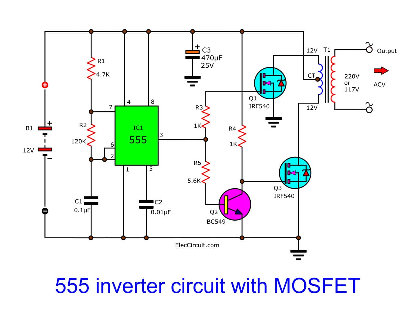
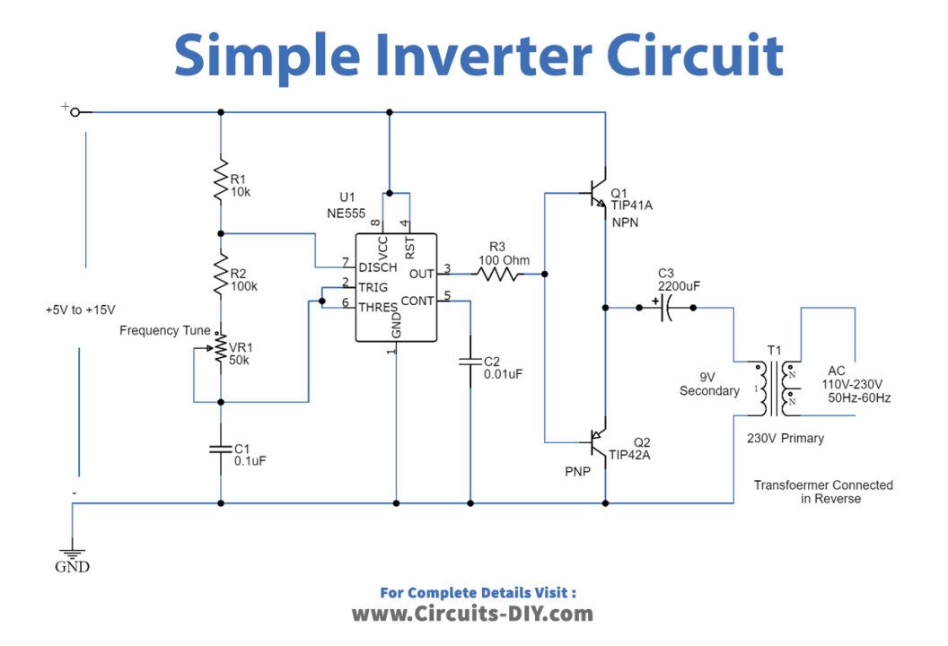
Make Simple 555 Inverter Circuit Using Mosfet Eleccircuit The 555 timer ic is used as the key component which is configured as an astable multivibrator to provide continuous switching pulses. the transformer has 230v 9v is used inverted to act as a step up transformer and is derived by the two transistors tip41a (npn) and tip42a (pnp). the input supply voltage is 5v to 15v dc and the output achieved. Ic 555 inverter circuit diagram. in this post we are going to construct a simple inverter using ic 555 timer. we will explore the proposed inverter circuit in depth and also we will learn how to debug the circuit at different stages to solve the issues that could arise with this inverter. we will see: full circuit diagram of ic 555 based inverter.

Simple Inverter Circuit Using 555 Timer First, you need to review the pin of the ic, resistors, and. capacitors. and importantly is how you connect the mosfet. view using irf540 legs. second, should do not connect the power cord to the transformer and mosfet. third, check the 555 timers working, and frequency generators at pin 3 first. Working explanation. here ic 555 is a main part of the circuit, it is employed as a switching pulse oscillator. for continuous switching pulse, 555 ic has to configure as astable multivibrator. the transformer t1 is 230v primary to 9v secondary but connected in reverse, so it can react as a step up transformer. Step 18: here is the final ac output with the tuned potentiometer: a 60 hz signal with a peak to peak voltage of 3.26 v. we have a be nice policy. please be positive and constructive. inverter: 5 vdc to ac with 555 timer: this tutorial will walk you through how to invert a dc voltage signal into an ac voltage signal using a 555 timer. Simple inverter circuit using ic 555 designed with few easily available components. we can create simple small inverter circuit to handle low power devices. the timer ic 555 oscillates high frequency square pulse and the transformer step up the pulse into high ac voltage. this circuit involves in handling of high ac voltage at output that can.

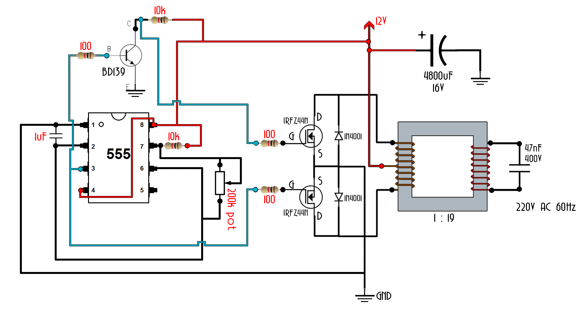
Diy 555 Inverter Timer Circuit Step 18: here is the final ac output with the tuned potentiometer: a 60 hz signal with a peak to peak voltage of 3.26 v. we have a be nice policy. please be positive and constructive. inverter: 5 vdc to ac with 555 timer: this tutorial will walk you through how to invert a dc voltage signal into an ac voltage signal using a 555 timer. Simple inverter circuit using ic 555 designed with few easily available components. we can create simple small inverter circuit to handle low power devices. the timer ic 555 oscillates high frequency square pulse and the transformer step up the pulse into high ac voltage. this circuit involves in handling of high ac voltage at output that can. Using ic 555 for the inverter. the diagram above shows the entire design of the proposed spwm inverter circuit using ic 555, where the center ic 555 and the associated bjt mosfet stages forms a basic square wave inverter circuit. our aim is to chop these 50hz square waves into the required spwm waveform using an opamp based circuit. The 555 timer ic is one of the most popular chips used in inverter circuits. with its easy to use interface, it can create a range of oscillatory signals, making it great for connecting to other components of an inverter circuit. in this article, we’ll go through the steps needed to build an inverter circuit diagram using a 555 timer.

Comments are closed.