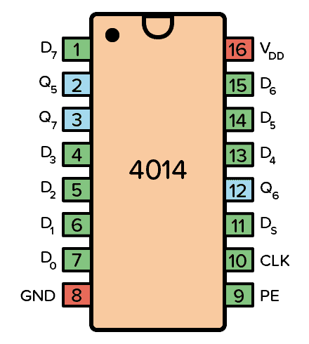
Ic Pin Diagram Pdf

List Of 4000 Series Ic Pinouts Functions Example Circuits And More 5. control. 555timer. discharge a 1 14 vs vcc. threshold a 2 13 discharge b. control a 3 12 threshold b. reset a 4 11 control b. output a 5 10 reset b. trigger a 6 9 output b. 74hc32. quadruple 2 input or gates. description. the 74hc32 provides provides four independent 2 input or gates with standard push pull outputs. the device is designed for operation with a power supply range of 2.0v to 6.0v. the gates perform the boolean function: y =a bor y =a•b.

Ic Pin Diagram Pdf Electrical characteristics (vcc = 5v to 15v, ta = 25°c unless otherwise stated) notes: 8. this parameter influences the maximum ≉ value of the timing resistors ra and rb in the circuit of figure 12. for example, when vcc = 5 v, the maximum value is r = ra rb 3.4mΩ, and for vcc = 15 v, the maximum value is 10mΩ. 9. Description. the 74hc08 provides provides four independent 2 input and gates. with standard push pull outputs. the device is designed for operation. with a power supply range of 2.0v to 6.0v. The lm555 can operate in both astable and monostable mode depending on the application requirements. • monostable mode: the lm555 timer acts as a “one shot” pulse generator. the pulse beings when the lm555 timer receives a signal at the trigger input that falls below a 1 3 of the voltage supply. The guts of an integrated circuit, visible after removing the top. the real "meat" to an ic is a complex layering of semiconductor wafers, copper, and other materials, which interconnect to form transistors, resistors or other components in a circuit. the cut and formed combination of these wafers is called a die.

Ic Pin Diagrams Pdf The lm555 can operate in both astable and monostable mode depending on the application requirements. • monostable mode: the lm555 timer acts as a “one shot” pulse generator. the pulse beings when the lm555 timer receives a signal at the trigger input that falls below a 1 3 of the voltage supply. The guts of an integrated circuit, visible after removing the top. the real "meat" to an ic is a complex layering of semiconductor wafers, copper, and other materials, which interconnect to form transistors, resistors or other components in a circuit. the cut and formed combination of these wafers is called a die. Here’s the internal schematics of 555 timer which consists of 25 transistors, 2 diodes and 15 resistors. represented with a block diagram it consists of 2 comparators, a flip flop, a voltage divider, a discharge transistor and an output stage. the voltage divider consists of three identical 5k resistors which create two reference voltages at. Integrated circuit pin layout. 74ls00 quad 2 in nand. 74ls02 quad 2 in nor. 74ls04 hex inverter. 74ls05 hex inverter. 74ls08 quad 2 in and. 74ls10 & 7410 tripple 3 in nand. 74ls11 triple 3 in and. 74ls27 triple 3 in nor.

Comments are closed.