How To Connect The Mcp3008 Analog To Digital Converter Adc To A Raspberry Pi And Arduino

Rpi Adc Mcp3008 Interface To The Mcp3008 Analog To Digital The mcp3008 is a low cost 8 channel 10 bit analog to digital converter. the precision of this adc is similar to that of an arduino uno, and with 8 channels you can read quite a few analog signals from the pi. this chip is a great option if you just need to read simple analog signals, like from a temperature or light sensor. In this episode we take a look at the mcp3008 analog to digital converter ic. with this chip we can add analog inputs to a raspberry pi, or extend the analog.

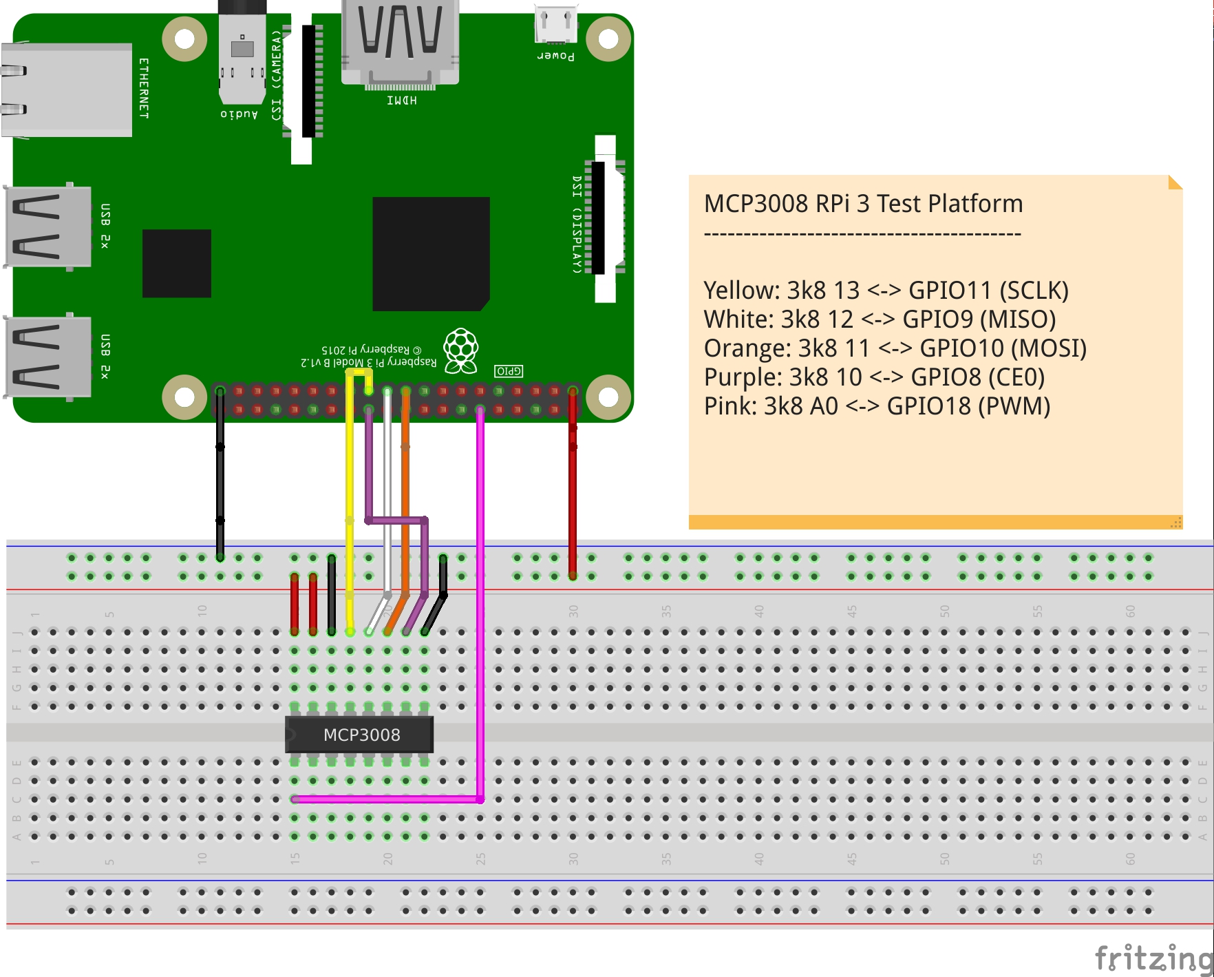
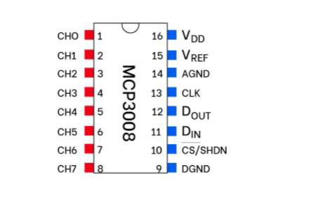
Mcp3008 Adc 10 Bit Analog To Digital Converter Guide In this example, i have included an ldr to show how you can get the value of the ldr back to the pi by using the analog to digital converter (adc). first, connect a 3v3 pin to the positive rail on the breadboard and a ground pin to the ground rail on the breadboard. also, place the mcp3008 chip into the middle of the breadboard. 1. enable spi. "sudo raspi config". select interfacing options. selet spi. 2. check to see if spi is activated. "lsmod" > should see something like spi 2835. 3. The mcp3008 chip is a 10 bit digital to analog converter that reads analog signals and sends them to a microcontroller via spi communication protocol (spi signals that the raspberry pi can read). the mcp3008 comes with 16 pins. half of those pins are analog inputs that you can use to connect to analog devices. Pin 3 (right) to gnd. potentiometer connections. potentiometer pin to connection. pin 1 (left) to 3.3v. pin 2 (middle) to mcp3008 ch0 (analog input #0) pin 3 (right) to gnd. this setup will allow the mcp3008 to interface with the raspberry pi and receive analog data from the potentiometer.

Mcp3008 Analog To Digital Converter Arduino Projects The mcp3008 chip is a 10 bit digital to analog converter that reads analog signals and sends them to a microcontroller via spi communication protocol (spi signals that the raspberry pi can read). the mcp3008 comes with 16 pins. half of those pins are analog inputs that you can use to connect to analog devices. Pin 3 (right) to gnd. potentiometer connections. potentiometer pin to connection. pin 1 (left) to 3.3v. pin 2 (middle) to mcp3008 ch0 (analog input #0) pin 3 (right) to gnd. this setup will allow the mcp3008 to interface with the raspberry pi and receive analog data from the potentiometer. The arduino uses usb while the mcp3008 uses spi. the arduino is all ready mounted and ready to use out of the box while the mcp3008 will need some accessories and work to get going. the mcp3008 is cheaper, but by the time you add in all the stuff you need (gpio break out, mounting breadboard ) the cost gap is not as large as it seems. In this example i have included an ldr to show how you can get the value on the pi using the analog to digital converter (adc). first connect a 3v3 pin to the positive rail on the breadboard and a ground pin to the ground rail on the breadboard. also place the mcp3008 chip into the middle of the breadboard. vdd (pin 16) wire this to 3.3v.

Comments are closed.