How To Apply Gdt Position Tolerance To A Hole

True Position Gd T Basics Quickly shows how to use gd&t to locate a simple clearance hole on a flat plate.instagram: @straighttothepointengineeringdiscord: discord.gg uvezyd. Quickly shows how to use gd&t to locate a circular pattern of clearance holes on a flat plate.instagram: @straighttothepointengineeringdiscord: dis.

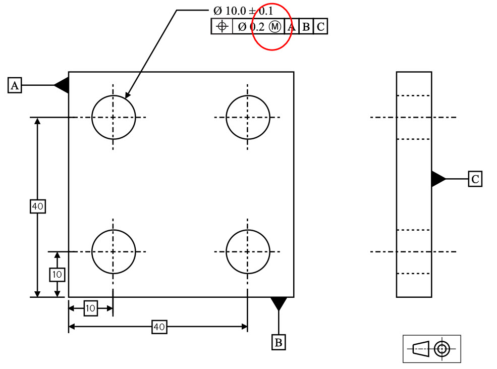
Position Tolerance Vs вђњtrue Positionвђќ Gd T Basics Definition of true position. the true position tolerance in gd&t informs us of the maximum allowable deviation of a feature (e.g. hole, slot) from its true position. by true position, we mean the ideal position of the feature according to design. the idea is that, for a feature, there is a true position that we desire. The 4 hole pattern: the holes in the pattern have a feature size tolerance of ±0.1 mm and a position tolerance of 0.5 mm at mmc with respect to datum reference frame abc. the position of these holes is defined using basic dimensions with respect to the datum reference frame abc. The following figures illustrate how tolerance of position controls the perpendicularity of a hole or a pin. the same principles apply if the tolerance of position is controlling a slot or a tab. the figure below shows first a perpendicularity and then a tolerance of position. True position = 2 x sqrt (xvar^2 yvar^2) so, we take the difference in x (difference between actual and measured x), square it, add that to the difference in y squared, take the square root of that sum and multiply by 2. let's say we're off by 0.0015 in both x and y. that gives us: true position = 2 x sqrt ( 0.0015^2 0.0015^2) = 0.004243.

Gd T Basics Introduction To Geometric Dimension And Tolerance The following figures illustrate how tolerance of position controls the perpendicularity of a hole or a pin. the same principles apply if the tolerance of position is controlling a slot or a tab. the figure below shows first a perpendicularity and then a tolerance of position. True position = 2 x sqrt (xvar^2 yvar^2) so, we take the difference in x (difference between actual and measured x), square it, add that to the difference in y squared, take the square root of that sum and multiply by 2. let's say we're off by 0.0015 in both x and y. that gives us: true position = 2 x sqrt ( 0.0015^2 0.0015^2) = 0.004243. Bonus tolerance explained: as the size of the pin departs from mmc toward lmc, a bonus tolerance is added equal to the amount of that departure. bonus tolerance equals the difference between the actual feature size and the mmc of the feature. in this case, bonus tolerance = mmc lmc=25 15=10. clearance for assembly increases if the actual sizes. The basic dimensions of 2.5” from the bottom of the part (datum feature b) and 2.5” from the left side (datum feature c) locate the perfect location for the axis of the hole – the true position of the hole. the tolerance on this location is indicated through the feature control frame for the hole. this feature control frame tells us that.

Comments are closed.