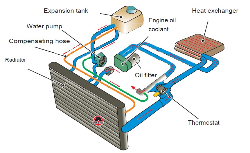
Forced Circulation Cooling System Diagram

Forced Circulation Thermostat Cooling System Youtube In this video, i explained forced circulation thermo stat cooling system of ic engine.i explained also explained following topic.1. construction of forced ci. Therefore, a pressure type radiator cap is used with the forced circulation cooling system. the cap is fitted on the radiator neck with an air tight seal. the pressure release valve or safety valve is set to open at a pressure between 4 and 13 psi.

Forced Circulation Water Cooling System The cooling system is a system of parts and fluid that work together to control an engine’s operating temperature for optimal performance. the system is made up of passages inside the engine block and heads, a water pump and drive belt to circulate the coolant, a thermostat to control the temperature of the coolant, a radiator to cool the. Thermosiphon. thermosiphon (or thermosyphon) is a method of passive heat exchange, based on natural convection, which circulates a fluid without the necessity of a mechanical pump. thermosiphoning is used for circulation of liquids and volatile gases in heating and cooling applications such as heat pumps, water heaters, boilers and furnaces. Schematic diagram of a forced circulation system forced circulation cooling system 21 the water or coolant is circulated through water jackets around the parts of the engine to be cooled, and is kept in motion by a centrifugal pump, driven from the engine. a thermostat is used to control the water temperature required for cooing. An important limitation of this system is that the cooling depends only on temperature and is independent of engine speed. also the circulation of water starts only after the engine has become hot enough to cause thermo syphon action. diagram of thermo syphon cooling system : thermo syphon cooling system. the advantages of thermo syphon cooling.

Forced Circulation Systems Schematic diagram of a forced circulation system forced circulation cooling system 21 the water or coolant is circulated through water jackets around the parts of the engine to be cooled, and is kept in motion by a centrifugal pump, driven from the engine. a thermostat is used to control the water temperature required for cooing. An important limitation of this system is that the cooling depends only on temperature and is independent of engine speed. also the circulation of water starts only after the engine has become hot enough to cause thermo syphon action. diagram of thermo syphon cooling system : thermo syphon cooling system. the advantages of thermo syphon cooling. This cooling system has different parts such as the radiator, fan, lower tank, upper tank, lower hose pipe connection, upper hose pipe connection, and cylinder water jacket as shown in the thermosyphon cooling system diagram. the thermosyphon cooling system is so designed that the water may circulate naturally because of the density difference. Transfer piping, as shown in figure 1. power utility services often use this type o f system. figure 1 . once through cooling water system diagram . 1.2 open recirculating cooling water systems. open recirculating cooling water systems are open to the atmosphere and continuously recycle and reuse the cooling water.

Engineering Projects Forced Circulation Cooling System This cooling system has different parts such as the radiator, fan, lower tank, upper tank, lower hose pipe connection, upper hose pipe connection, and cylinder water jacket as shown in the thermosyphon cooling system diagram. the thermosyphon cooling system is so designed that the water may circulate naturally because of the density difference. Transfer piping, as shown in figure 1. power utility services often use this type o f system. figure 1 . once through cooling water system diagram . 1.2 open recirculating cooling water systems. open recirculating cooling water systems are open to the atmosphere and continuously recycle and reuse the cooling water.

Forced Circulation Evaporator Principle Construction And Working

Comments are closed.