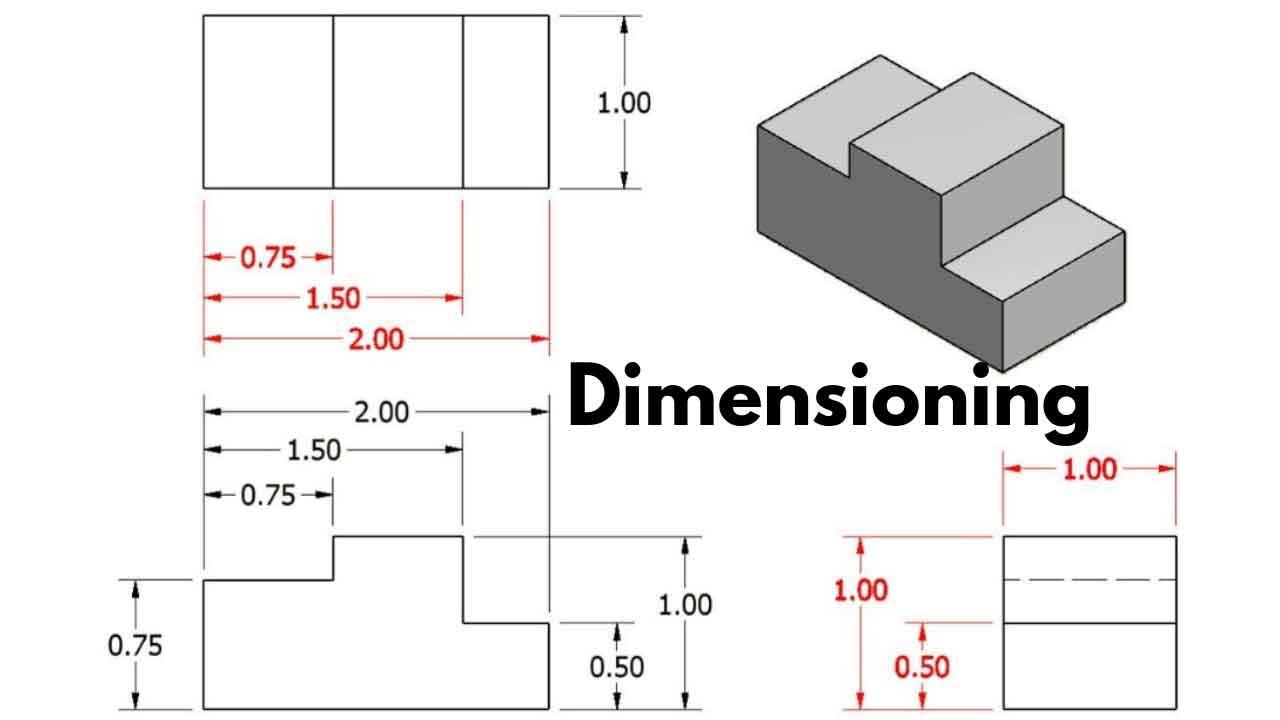
Engineering Drawing Dimensioning

Dimensioning In Engineering Drawing No 1 Detailed Guide 2023 Learn the basics of graphics communication and dimensioning for engineering drawings, including the alphabet of lines, dimension elements, and dimensioning practice. find out the rules, symbols, and units of measurement for dimensioning in different views and cases. Learn about the elements, units, common features and methods of dimensioning in engineering drawings. find out the difference between aligned and unidirectional systems, and the types of dimensioning such as chain, parallel, combined, etc.

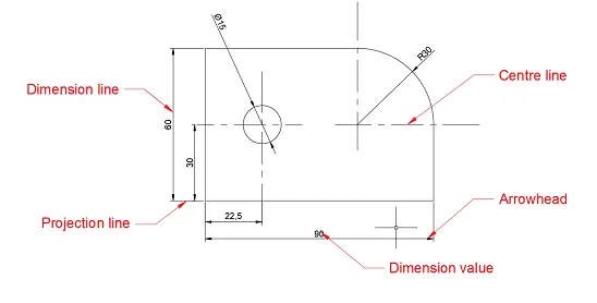
Dimensioning In Engineering Drawings Ken Institute 1. basic requirements for dimensioning of assembly. 1. the dimensions shall be complete, and the shape and size of the object shall be completely determined without omission or repetition. 2. the dimensions shall comply with the provisions of national standards, that is, strictly abide by national standards. 3. However, the convention in a drawing is to show the view on the left as the preferred method for sectioning this type of object. figure 22 cross section. dimensioning. the purpose of dimensioning is to provide a clear and complete description of an object. a complete set of dimensions will permit only one interpretation needed to construct. In this video, we are going to learn about dimensions in engineering drawing! we are going to look at what dimensioning is, what are the elements of the dime. Engineering drawings employ various types of dimensions to convey different aspects of a design. understanding these types and their appropriate applications is crucial for effective dimensioning. linear dimensions: these are the most common type of dimension and are used to specify the length, width, or height of a feature.

1 4a Placing Of Dimension Systems In Engineering Drawing Aligned And In this video, we are going to learn about dimensions in engineering drawing! we are going to look at what dimensioning is, what are the elements of the dime. Engineering drawings employ various types of dimensions to convey different aspects of a design. understanding these types and their appropriate applications is crucial for effective dimensioning. linear dimensions: these are the most common type of dimension and are used to specify the length, width, or height of a feature. This is done to avoid confusion with other lines. never draw leader lines entirely horizontal or vertical. quiz. directions: complete as indicated. dimension this drawing. the dimensions are 3” long, 2 1 8” wide, 1 5 8” high with a 45 angle ½” deep. the angle begins as the midpoint of the 3” long dimension. Dimensioning is a crucial aspect of engineering drawings, which plays an essential role in communicating design specifications and requirements to manufacturers, engineers, and other stakeholders. essentially, dimensioning refers to the process of specifying the exact size, shape, and location of different parts and features on an engineering drawing.

Rules Of Dimensioning In Engineering Drawing This is done to avoid confusion with other lines. never draw leader lines entirely horizontal or vertical. quiz. directions: complete as indicated. dimension this drawing. the dimensions are 3” long, 2 1 8” wide, 1 5 8” high with a 45 angle ½” deep. the angle begins as the midpoint of the 3” long dimension. Dimensioning is a crucial aspect of engineering drawings, which plays an essential role in communicating design specifications and requirements to manufacturers, engineers, and other stakeholders. essentially, dimensioning refers to the process of specifying the exact size, shape, and location of different parts and features on an engineering drawing.

Comments are closed.