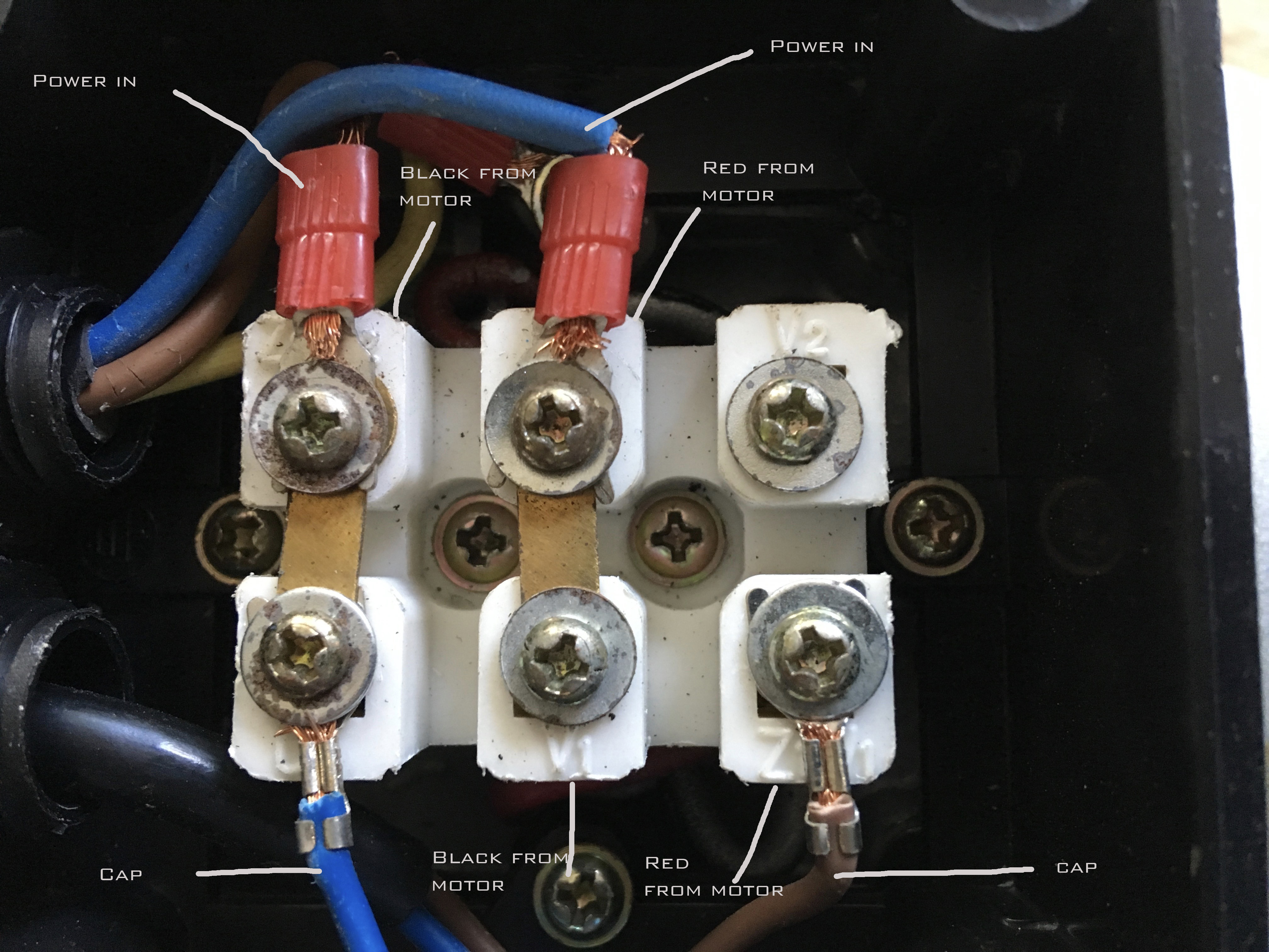
Electric Motor Wiring Connection

Electric Motor Wiring Connections Step 1: identify the motor’s wires. before beginning the wiring process, take a moment to identify the different wires coming from the motor. typically, you will find three main wires: the power wire, the neutral wire, and the ground wire. the power wire is usually black, the neutral wire is white, and the ground wire is usually green or bare. The y connection, also known as a star connection or a wye connection, is a common method of connecting electric motors. it allows for a balanced distribution of electrical currents and is commonly used in three phase systems. in a y connection, the three motor windings are connected to form a y shape.

Electric Motor Wiring Diagrams Explained Begin by identifying the motor connections. a typical electric motor has several terminal connections, including power supply, ground, and control connections. refer to the motor’s wiring diagram to determine the specific terminals for each connection. step 3: connect the power supply. start by connecting the power supply. Electrical motor connections. how electric motors work, electrical motor connections explained, star delta wye electrical connections on three phase motors. An electric motor wiring diagram is a visual representation of the electrical connections and components in an electric motor. it shows how the various wires and terminals are connected, allowing technicians and electricians to understand the motor’s wiring and troubleshoot any issues that may arise. The wiring diagram for a 3 phase motor shows how the motor’s three windings are connected to the power supply and control circuits. each winding corresponds to one phase of the electrical system, and the proper phasing and sequencing of these windings is crucial for the motor’s operation. the wiring diagram typically includes information.

Electric Motor Wiring Connection An electric motor wiring diagram is a visual representation of the electrical connections and components in an electric motor. it shows how the various wires and terminals are connected, allowing technicians and electricians to understand the motor’s wiring and troubleshoot any issues that may arise. The wiring diagram for a 3 phase motor shows how the motor’s three windings are connected to the power supply and control circuits. each winding corresponds to one phase of the electrical system, and the proper phasing and sequencing of these windings is crucial for the motor’s operation. the wiring diagram typically includes information. Motor wiring diagrams. wiring diagrams show the conductive connections between electrical apparatus. they show the internal and or external connections but, in general, do not give any information on the mode of operation. instead of wiring diagrams, wiring tables can also be used. unit wiring diagram – representation of all the connections. A motor wiring diagram is a schematic representation of the electrical connections and components involved in the operation of an electric motor. it shows how the various wires and terminals are connected, allowing technicians and electricians to understand the motor’s circuitry and troubleshoot any potential issues.

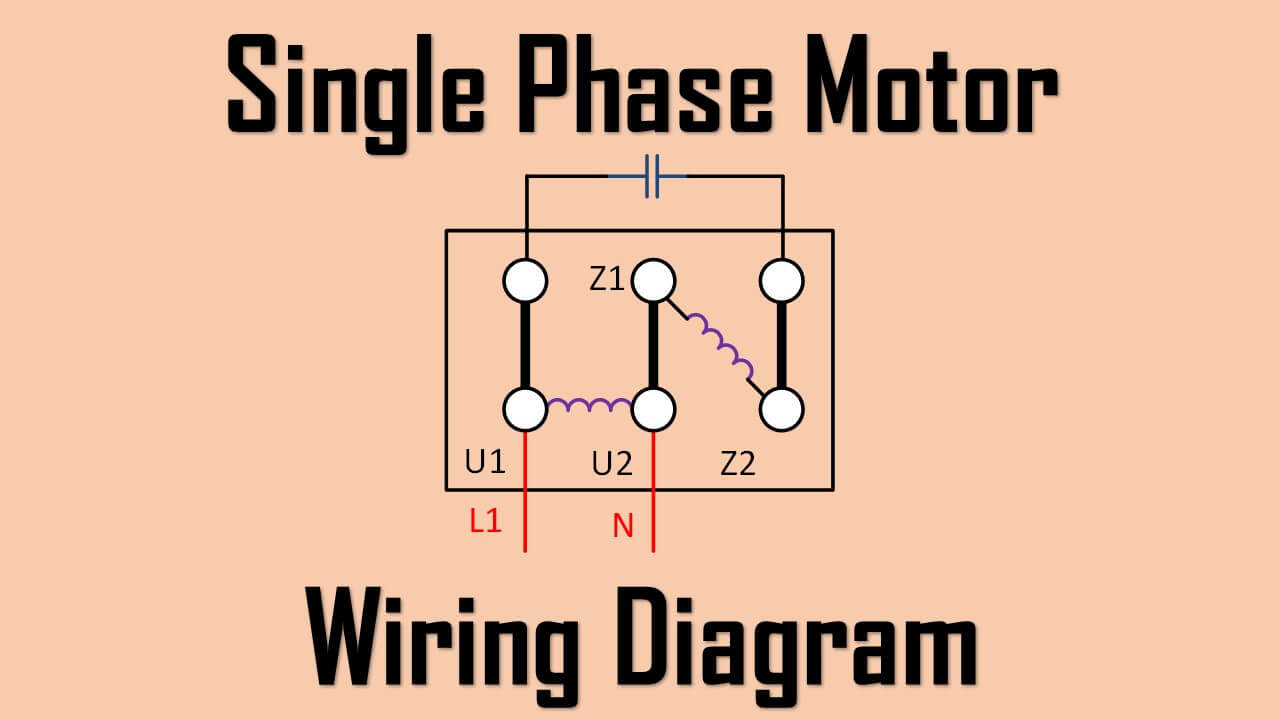
Single Phase Motor Wiring Diagram And Examples вђ Wira Electrical Motor wiring diagrams. wiring diagrams show the conductive connections between electrical apparatus. they show the internal and or external connections but, in general, do not give any information on the mode of operation. instead of wiring diagrams, wiring tables can also be used. unit wiring diagram – representation of all the connections. A motor wiring diagram is a schematic representation of the electrical connections and components involved in the operation of an electric motor. it shows how the various wires and terminals are connected, allowing technicians and electricians to understand the motor’s circuitry and troubleshoot any potential issues.

Electric Motor Wiring Schematics

Comments are closed.