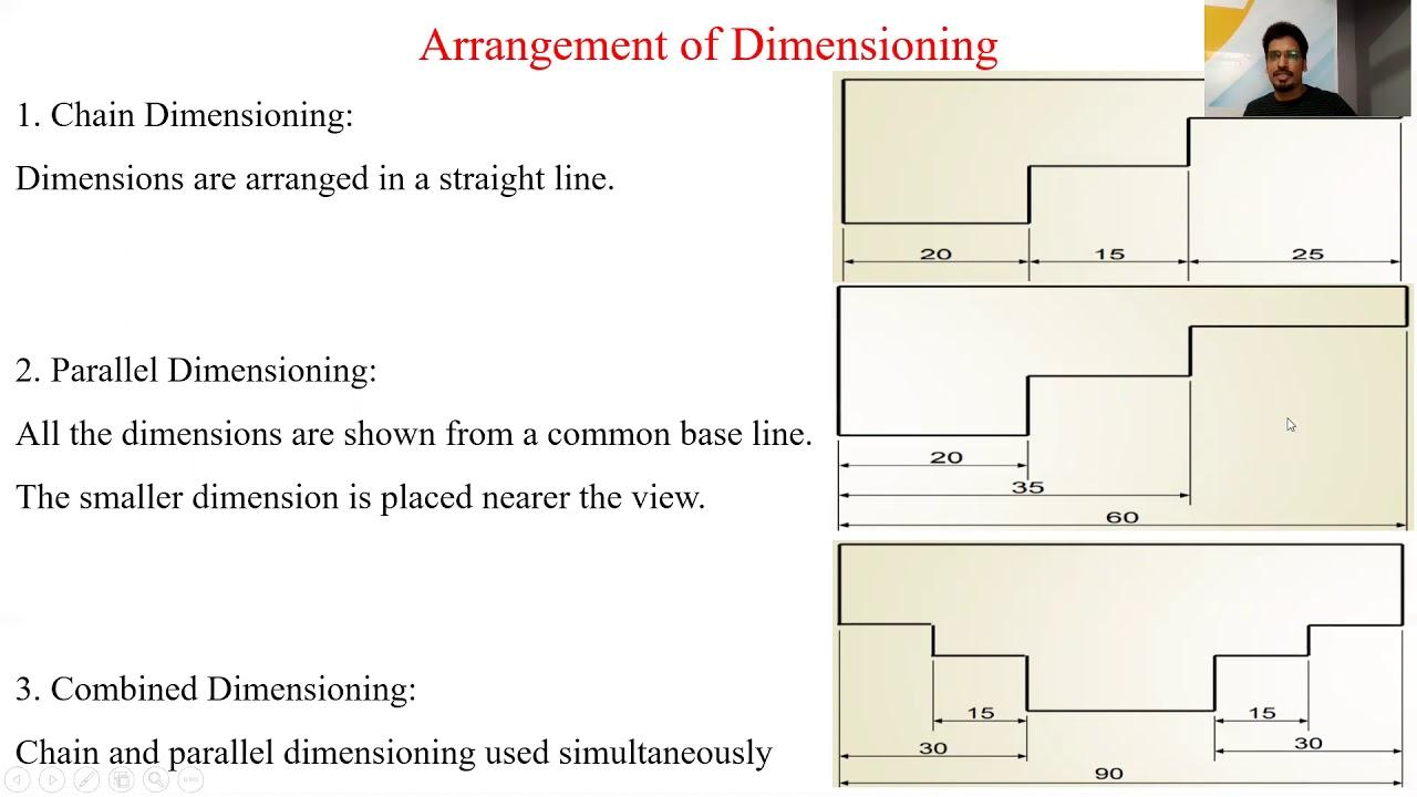
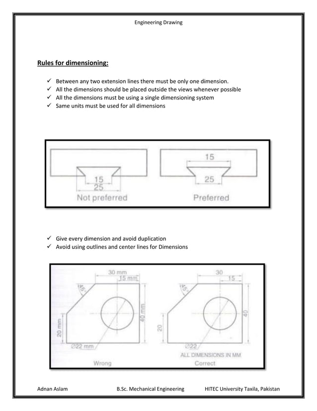
Dimensioning Part 1 In Engineering Drawingаґ Dimensioning Basics

Engineering Drawing Dimensioning Part 1 Youtube Diameters must be dimensioned with the diameter symbol preceding the numerical value. when holes are dimensioned with a leader line, the line must be radial. a radial line is one that passes through the center of a circle or arc if extended. symbols may be used for spotface, counterbore, and countersunk holes. 1. basic requirements for dimensioning of assembly. 1. the dimensions shall be complete, and the shape and size of the object shall be completely determined without omission or repetition. 2. the dimensions shall comply with the provisions of national standards, that is, strictly abide by national standards. 3.

Edu Support This document discusses dimensioning practices for engineering drawings. it begins by defining dimensioning as specifying part sizes, locations, materials, tolerances and other information using figures, symbols and notes. it then covers components of dimensioning like extension lines, dimension lines, leader lines and dimension figures. Presentation transcript: 1 engineering drawing and design chapter 10 basic dimensioning. 2 basic dimensioning dimensions are given on drawings by extension lines, dimension lines, leaders, arrowheads, figures, notes and symbols length diameter angle location not duplicated dimension lines are used to determine the extent and direction of. Dimensioning geometrics is the science of specifying and tolerancing the shapes and locations of features on objects. once the shape of a part is defined with an orthographic drawings, the size information is added also in the form of dimensions. dimensioning a drawing also identifies the tolerance (or accuracy) required for each dimension. Basic elements for dimensioning technical drawinings. the following figures show basic elements of dimensioning, according to din iso 129 1. basic dimensioning basic dimensioning. every distance is described in technical drawings using this dimensioning. a complete measurement consists of a measure line, measure aid lines, measure arrows and a.

Dimensioning In Engineering Drawings Ken Institute Dimensioning geometrics is the science of specifying and tolerancing the shapes and locations of features on objects. once the shape of a part is defined with an orthographic drawings, the size information is added also in the form of dimensions. dimensioning a drawing also identifies the tolerance (or accuracy) required for each dimension. Basic elements for dimensioning technical drawinings. the following figures show basic elements of dimensioning, according to din iso 129 1. basic dimensioning basic dimensioning. every distance is described in technical drawings using this dimensioning. a complete measurement consists of a measure line, measure aid lines, measure arrows and a. Essentially, dimensioning refers to the process of specifying the exact size, shape, and location of different parts and features on an engineering drawing. dimensioning is vital in the engineering industry as it ensures that the final product meets the required standards and specifications. it helps to minimize errors and inaccuracies during. This steel plate is 70mm long, 35 mm wide, and 7 mm high. you probably noticed these thin lines with the arrows on the sides and the number in the middle (or on the side). this is how we represent dimensions on the engineering drawings. the rules for dimensioning are defined by iso 129 1:2018.

Basics Of Engineering Drawing Dimensioning Projections Principle Views Essentially, dimensioning refers to the process of specifying the exact size, shape, and location of different parts and features on an engineering drawing. dimensioning is vital in the engineering industry as it ensures that the final product meets the required standards and specifications. it helps to minimize errors and inaccuracies during. This steel plate is 70mm long, 35 mm wide, and 7 mm high. you probably noticed these thin lines with the arrows on the sides and the number in the middle (or on the side). this is how we represent dimensions on the engineering drawings. the rules for dimensioning are defined by iso 129 1:2018.

Comments are closed.