Depletion Mosfet Circuit Diagram

Depletion Type Mosfet Circuit Diagram Circuit Diagram Applications for depletion mosfets how to use a depletion mosfet 2.3 inear regulators a depletion mosfet can also be used as a pass transistor for a linear regulator. figure 10 shows a linear regulator circuit using a depletion mosfet plus a zener diode. in the circuit, q 1 acts as a source follower where the source voltage follows the gate. Circuit will then go into dormant state to conserve power. figure 5 shows a starting circuit using a depletion fet, a resistor and a zener diode. the depletion fet and resistor circuit functions as a current limiter for the current in the zener diode. the voltage at the source of the depletion fet is at v z v gs(th), approximately 10.5v.

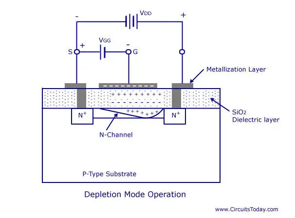
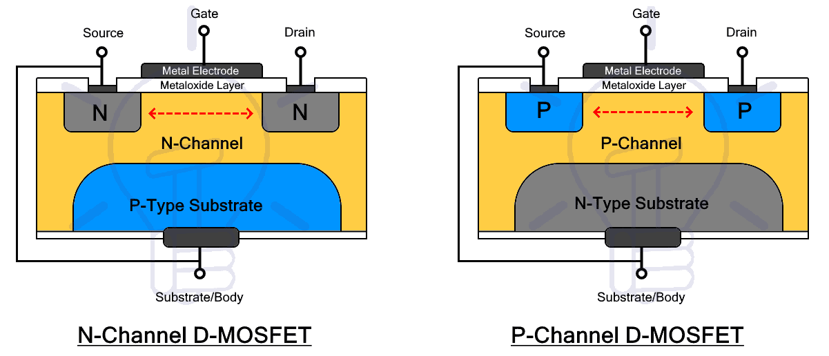
Depletion Mosfet Circuit Diagram The metal oxide semiconductor field effect transistor or mosfet is a voltage controlled device that is constructed with terminals like source, drain, gate & body to amplify or switch voltages within circuits and is also extensively used in ics for digital applications. these are also used in analog circuits like amplifiers and filters. April 2, 2024. by ravi teja. in this tutorial, we will have a brief introduction to mosfet i.e., the metal oxide semiconductor field effect transistor. we will learn about different types of mosfet (enhancement and depletion), its internal structure, an example circuit using mosfet as a switch and a few common applications. outline. Notice how the above circuit looks like a simple npn regulator. there is one big difference, though: with the npn regulator, the output voltage is at vz 0.6v. with the depletion fet, the output voltage is vz vgsth. the clamped output is above the reference. another example of overvoltage protection usage, with a regulator:. An introduction to depletion mode mosfets. since the mid nineteen seventies the “enhancement mode” mosfet has been the subject of almost continuous global research, development, and refinement by both the semiconductor industry and academia. as a result it has become the predominant mosfet topology that encompasses discrete mos power.

N Channel Depletion Mosfet Circuit Diagram Notice how the above circuit looks like a simple npn regulator. there is one big difference, though: with the npn regulator, the output voltage is at vz 0.6v. with the depletion fet, the output voltage is vz vgsth. the clamped output is above the reference. another example of overvoltage protection usage, with a regulator:. An introduction to depletion mode mosfets. since the mid nineteen seventies the “enhancement mode” mosfet has been the subject of almost continuous global research, development, and refinement by both the semiconductor industry and academia. as a result it has become the predominant mosfet topology that encompasses discrete mos power. The zero bias of fig. 13.72(a) is unique with depletion mode mosfets. although any of the jfet biasing method will work with a depletion type mosfet, the zero bias method shown in fig. 13.72(a) is preferred as it does the job simply and adequately. after biasing the depletion type mosfet to a q point, it can amplify small signals. In a depletion mode mosfet, the device is normally on at zero gate–source voltage. such devices are used as load "resistors" in logic circuits (in depletion load nmos logic, for example). for n type depletion load devices, the threshold voltage might be about −3 v, so it could be turned off by pulling the gate 3 v negative (the drain, by.

Comments are closed.