Dd15 Coolant Lines Diagram

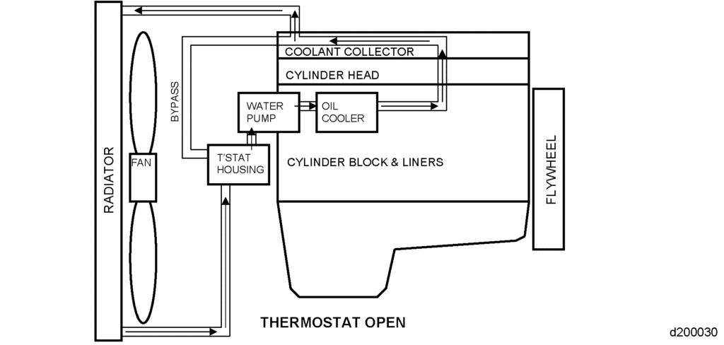
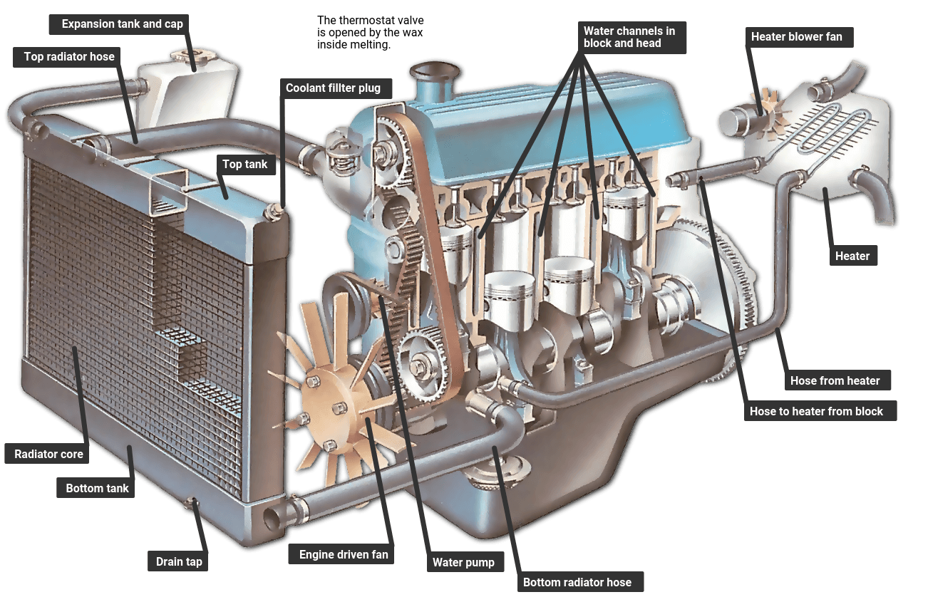
Dd15 Coolant System Diagram Issues And Maintenance Tips The cooling system is an essential component of a dd15 engine, designed to regulate the temperature and prevent the overheating of various engine parts. understanding the cooling system diagram is crucial for efficient maintenance and troubleshooting of the engine. the cooling system relies on a series of interconnected components and processes. The dd15 coolant hose diagram is a crucial reference tool for understanding the layout and flow of coolant within the dd15 engine system. this diagram provides a detailed visual representation of all the coolant hoses and their connectors, allowing technicians and mechanics to identify the correct routing and connections for coolant flow.

The Ultimate Guide To Understanding The Dd15 Cooling System Diagrams The dd15 coolant hose diagram is a visual representation of the coolant system in the dd15 engine, a heavy duty engine commonly used in commercial trucks. the coolant system is responsible for keeping the engine cool and preventing it from overheating. a properly functioning coolant system is crucial for the engine’s performance and longevity. N the cooling system enough t. e. pty the ht2 line.4. remove the ht2 line and hose.5. remove the threaded fitting for the epa07 ht2 line from. th. heater return manifold, or shutoff valve if used.6. install the new hos. b. rb in the heater return manifold or shutoff valve.7. i. st. ll the formed hose on the left side of the en. Learn how to fix a coolant leak on your freightliner cascadia with this video tutorial. see the steps to remove and replace the coolant hoses and verfichero. 20. install the egr hot pipe onto the egr cooler and the egr valve with two new spherical clamps and tighten clamp bolts to 12 n·m (9 lb·ft). refer to section "installation of the exhaust gas recirculation hot pipe". 21. install the turbocharger heat shield. 22. install the coolant line to the egr valve actuator and egr cooler water manifold.

Dd15 Cooling System Diagram Diagramwirings Learn how to fix a coolant leak on your freightliner cascadia with this video tutorial. see the steps to remove and replace the coolant hoses and verfichero. 20. install the egr hot pipe onto the egr cooler and the egr valve with two new spherical clamps and tighten clamp bolts to 12 n·m (9 lb·ft). refer to section "installation of the exhaust gas recirculation hot pipe". 21. install the turbocharger heat shield. 22. install the coolant line to the egr valve actuator and egr cooler water manifold. Detroit™ gen 5 heavy duty dd15 major engine components are shown below: water pump. oil coolant module. oil filter. high pressure fuel rail. air intake manifold. hydrocarbon fuel doser block. high pressure fuel pump. air compressor. 1 04 07 17. subject date ghg17 heavy duty exhaust & egr egr actuator coolant lines april 2017. additions, revisions, or updates. publication number title platform section title change ddc svc man 0190 ghg17 heavy duty dd13 15 16 removal of the dd13 and dd15 egr valve actuator coolant return line new sections.

Dd15 Coolant System Diagram At Sandra Reel Blog Detroit™ gen 5 heavy duty dd15 major engine components are shown below: water pump. oil coolant module. oil filter. high pressure fuel rail. air intake manifold. hydrocarbon fuel doser block. high pressure fuel pump. air compressor. 1 04 07 17. subject date ghg17 heavy duty exhaust & egr egr actuator coolant lines april 2017. additions, revisions, or updates. publication number title platform section title change ddc svc man 0190 ghg17 heavy duty dd13 15 16 removal of the dd13 and dd15 egr valve actuator coolant return line new sections.

Dd15 Coolant Lines Diagram Diagramwirings

Comments are closed.