Dc To Ac Inverter Circuit Diagram Using 555 Timer Pdf Circuit

Dc To Ac Inverter Circuit Diagram Using 555 Timer Pdf Circuit Diagram Step 18: here is the final ac output with the tuned potentiometer: a 60 hz signal with a peak to peak voltage of 3.26 v. we have a be nice policy. please be positive and constructive. inverter: 5 vdc to ac with 555 timer: this tutorial will walk you through how to invert a dc voltage signal into an ac voltage signal using a 555 timer. 5 application. in this tutorial, we are going to make an “inverter circuit using ic 555 “. an inverter is nothing but a dc to ac converter ( a power electronic device or circuitry that changes direct current (dc) to alternating current (ac). the resulting ac frequency obtained depends on the particular device employed).

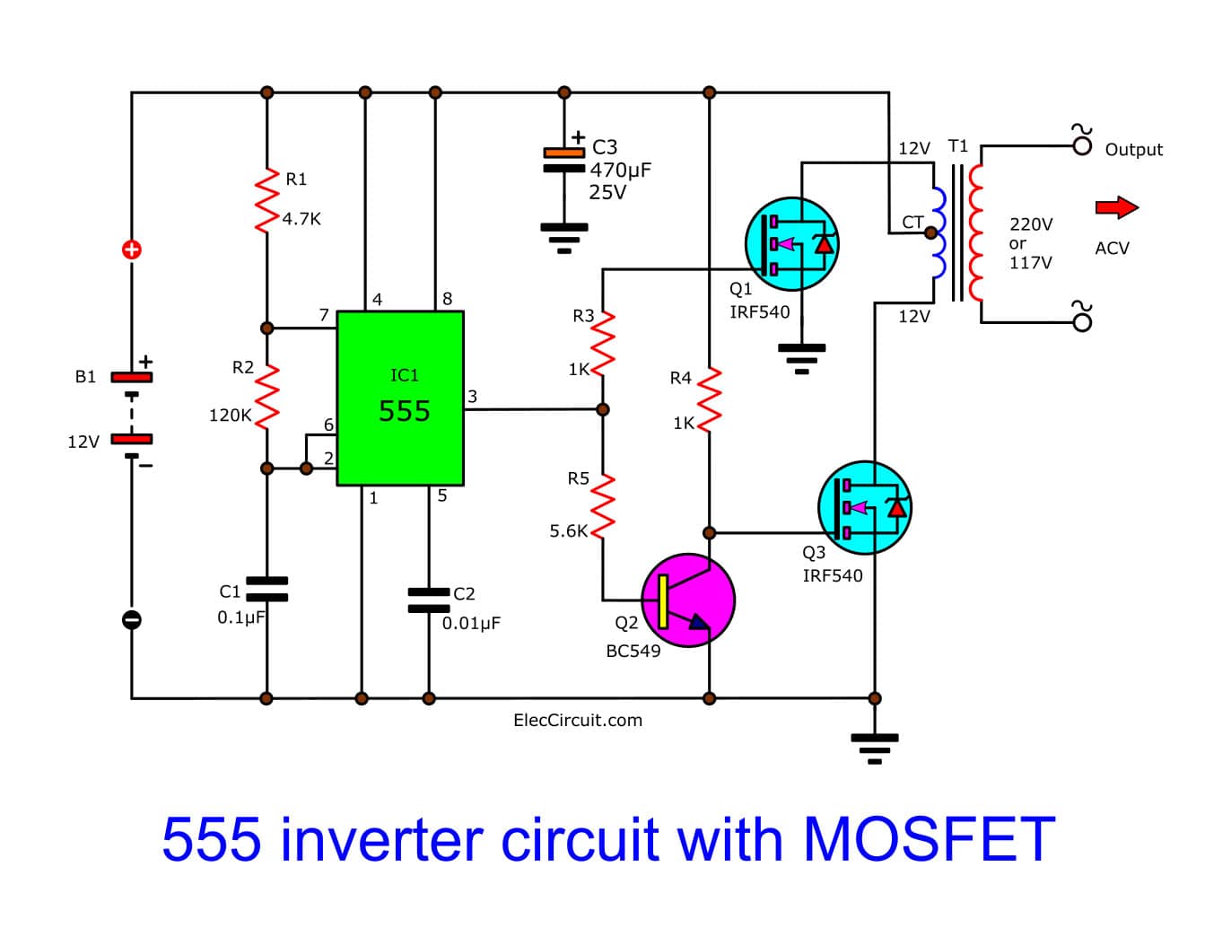
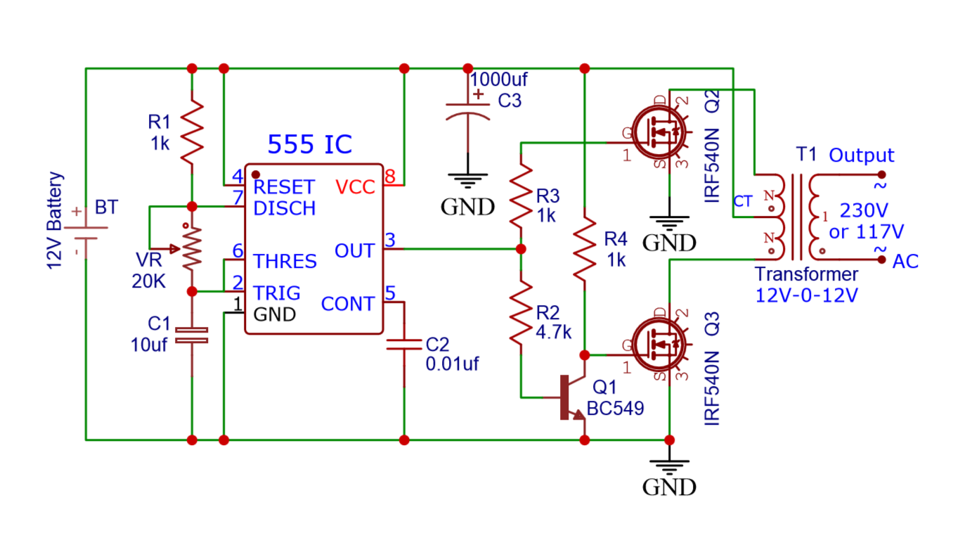
Make Simple 555 Inverter Circuit Using Mosfet Eleccircuit Next, connect the transistor circuit’s base to one of the 555 timer’s inverter output pins. then connect the collector of the transistor circuit to the ac input voltage of the inverter. finally, connect the emitter of the transistor circuit to the ground. all of these components must be properly connected in order for the circuit to. It consists of a 555 timer ic and simply 2 transistors. inverter is used to convert low voltage direct current (dc) to high voltage alternating current (ac). 123 circuits is a collection of electronics projects and simple electronic circuits make with pcb, for electronics beginners, hobbyist and students. electronic circuits and projects with. Simple inverter circuit using ic 555 designed with few easily available components. we can create simple small inverter circuit to handle low power devices. the timer ic 555 oscillates high frequency square pulse and the transformer step up the pulse into high ac voltage. this circuit involves in handling of high ac voltage at output that can. Ic 555 inverter circuit diagram. in this post we are going to construct a simple inverter using ic 555 timer. we will explore the proposed inverter circuit in depth and also we will learn how to debug the circuit at different stages to solve the issues that could arise with this inverter. we will see: full circuit diagram of ic 555 based inverter.

Dc To Ac Inverter Circuit Diagram Using 555 Timer ођ Simple inverter circuit using ic 555 designed with few easily available components. we can create simple small inverter circuit to handle low power devices. the timer ic 555 oscillates high frequency square pulse and the transformer step up the pulse into high ac voltage. this circuit involves in handling of high ac voltage at output that can. Ic 555 inverter circuit diagram. in this post we are going to construct a simple inverter using ic 555 timer. we will explore the proposed inverter circuit in depth and also we will learn how to debug the circuit at different stages to solve the issues that could arise with this inverter. we will see: full circuit diagram of ic 555 based inverter. The 555 timer ic is used as the key component which is configured as an astable multivibrator to provide continuous switching pulses. the transformer has 230v 9v is used inverted to act as a step up transformer and is derived by the two transistors tip41a (npn) and tip42a (pnp). the input supply voltage is 5v to 15v dc and the output achieved. The formula for calculating the rc values in a ic 555 circuit is shown below: f = 1.44 (r1 2 x r2) c. where f is the intended frequency output, r1 is the resistor which is connected between pin#7 and ground in the circuit, while r2 is the resistor in between pin#7 and pin#6 2 of the ic. c is the capacitor found between pin#6 2 and ground.

Dc To Ac Inverter Circuit Diagram Using 555 Timer ођ The 555 timer ic is used as the key component which is configured as an astable multivibrator to provide continuous switching pulses. the transformer has 230v 9v is used inverted to act as a step up transformer and is derived by the two transistors tip41a (npn) and tip42a (pnp). the input supply voltage is 5v to 15v dc and the output achieved. The formula for calculating the rc values in a ic 555 circuit is shown below: f = 1.44 (r1 2 x r2) c. where f is the intended frequency output, r1 is the resistor which is connected between pin#7 and ground in the circuit, while r2 is the resistor in between pin#7 and pin#6 2 of the ic. c is the capacitor found between pin#6 2 and ground.

Comments are closed.