Counter Sink Reference On Drawing

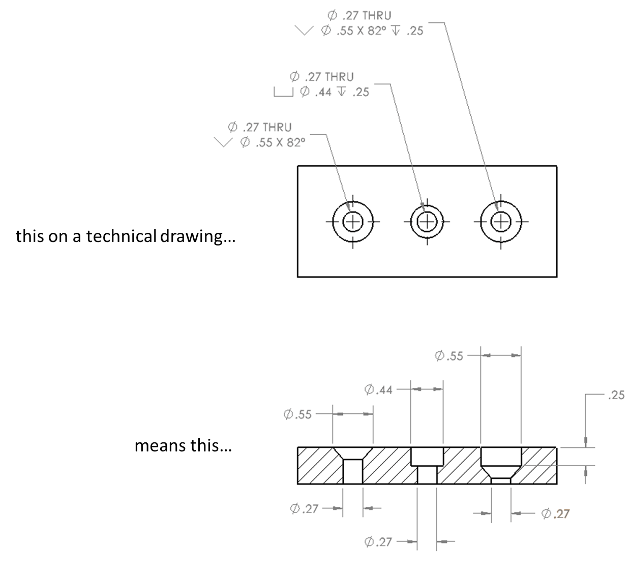
The Benefits Of Countersinking Sendcutsend The countersink dimension contains the countersink symbol, the diameter of the countersink, and the angle of the cone. in the example below, the part contains two thru holes with countersinks. the diameter of the thru holes is listed as 9 0.25, and the countersink is called out as a diameter of 19 0.5 with a conical angle of 90 degrees. 07 oct 2022. this is a complete guide to the types of holes found in machining. in this guide you’ll learn: the different types of holes used in machining. what the difference is between counterbore and countersink holes. the symbols used for each hole and how they are shown on engineering drawings. how each type of hole is used in engineering.

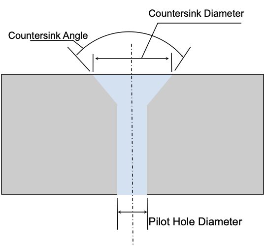
Dimensioning And Locating Advanced Features A countersink and a chamfer are very similar. a countersink is basically no different than a chamfer on a hole. the main difference is that a chamfer is normally thought of as being at 45 degrees (though the angle can vary). a countersink is usually one of many different standard angle sizes. the most common countersink angles are 82°, 90° or. 1.1 symbols permit consistency in the way dimensions and tolerances are specified, and each symbol has a clearly defined meaning. symbols take less time to apply on a drawing than would be required to state the same requirements with words. the symbols also require considerably less space. see figure 1. figure 1. 1.definition and purpose of countersink holes. the primary function of a countersink hole is to create a recess that accommodates the shape of the fastener head. by recessing the fastener, it avoids protrusion, allowing the material to sit flat against another surface or providing a clean finish. Calling out a countersink in a drawing requires the 3 dimensions to be called out along with the appropriate gd&t symbols. the symbol for a countersink is “v”, and here’s an example call out from a control drawing. Ø 0.25. v 0.5 ±0.005 х 90॰ the above calls out a 0.25dia pilot hole diameter, 0.5dia countersink diameter with a.

Countersink Holes What They Are When To Use Them Fictiv 1.definition and purpose of countersink holes. the primary function of a countersink hole is to create a recess that accommodates the shape of the fastener head. by recessing the fastener, it avoids protrusion, allowing the material to sit flat against another surface or providing a clean finish. Calling out a countersink in a drawing requires the 3 dimensions to be called out along with the appropriate gd&t symbols. the symbol for a countersink is “v”, and here’s an example call out from a control drawing. Ø 0.25. v 0.5 ±0.005 х 90॰ the above calls out a 0.25dia pilot hole diameter, 0.5dia countersink diameter with a. Is repeated on the drawing. parallelism is the condio n of a surface, line, or axis, which is equidistant at all points from a datum plane or axis. par ng lines [asme y14.5 2009 sec on 3.14] are depicted on casn g forging molded part drawings as a phantom line extending beyond the part in applicable views, with the parn g line symbol added. Choose a countersink tool with a slightly larger diameter than the drilled hole for effective deburring. 3. technique: insert the countersink tool into the drilled hole and rotate it with consistent pressure. the goal is to lightly shave off the burrs without altering the hole size or shape.

Comments are closed.