Cooling Tower Flow Diagram With Expansion Tank

Expansion Of Cooling Tower Systems Condenser water return pipework [1] the cooling tower return pipework is installed to transport the warm water from the condenser side of the water cooled chiller to the cooling tower, with the flow being provided by the condenser water pumps that are installed on the supply side of the tower [tower to chiller] to move the water around the system. This guide covers the design and selection of an expansion tank within an overall chilled water system. the expansion tank is a part of an overall chilled water system that often includes a chiller, piping, valves fittings, chilled water pump, air handling units and fan coil units. figure 0: this figure shows an overall chilled water system.

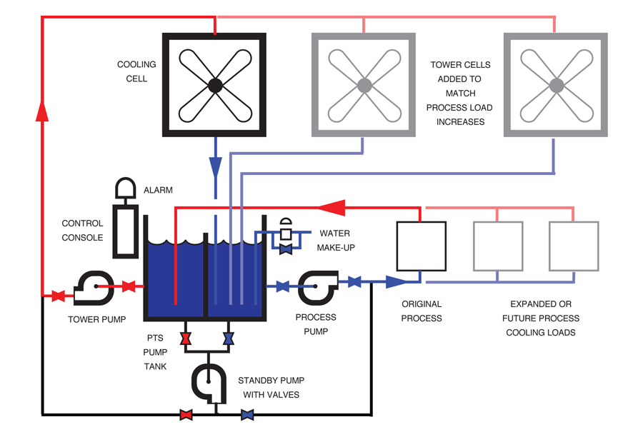
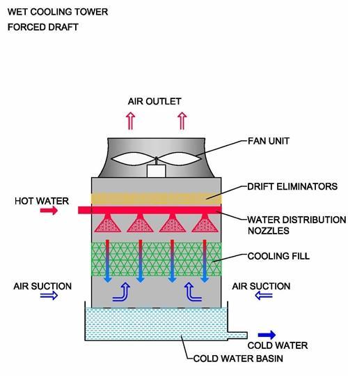
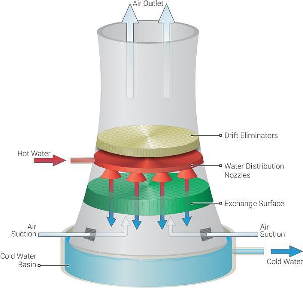
Cooling Tower Diagram A Go To Guide To Learn About Their Function Sequence of operation. when the operating fan(s) are operating at 50 percent speed, an additional fan shall be enabled and controlled at the same speed as the operating fans until all active cooling tower cell fans are enabled. when operating fans are running at minimum speed and the tower supply water temperature is five (5) degrees below the. Design capacity – 430.0 gpm design head – 47.0 feet motor size – 10 hp. less than anticipated pump headthe pump point shift has increased flow. over design to the order of 45%. cavitational and or tower vortex can occur unless. corrective measures are applied.the pump impeller diameter could, and should be cut down. Benefits of cooling tower flow diagram. a cooling tower flow diagram is a visual representation of the flow of water and air in a cooling tower system. it provides a clear understanding of how the cooling tower operates and helps in identifying potential issues or inefficiencies in the system. there are several benefits of using a cooling tower. 1.0 introduction. an expansion tank is used in a chilled water system to accomplish three main tasks, (1) accommodate thermal expansion of the chilled water, (2) maintain positive pressure at all points in the system at all times and (3) maintain net positive suction head at the chilled water pump(s).

Cooling Tower Schematic Diagram Benefits of cooling tower flow diagram. a cooling tower flow diagram is a visual representation of the flow of water and air in a cooling tower system. it provides a clear understanding of how the cooling tower operates and helps in identifying potential issues or inefficiencies in the system. there are several benefits of using a cooling tower. 1.0 introduction. an expansion tank is used in a chilled water system to accomplish three main tasks, (1) accommodate thermal expansion of the chilled water, (2) maintain positive pressure at all points in the system at all times and (3) maintain net positive suction head at the chilled water pump(s). Crossflow cooling towers flow diagram in crossflow cooling tower systems the water vertically flows through the fill media while the air horizontally flows across the falling water. that's why they call it "crossflow" because the air and water cross paths or flows. because of the crossing of flows, the air doesn't need to. This handbook, with its focus on water treatment, considers exchangers with water as the primary coolant, and where the water flow is through the tubes with the process fluid on the external tube surfaces. the design in figure 6.37 is co current with the coolant and process fluid flowing in the same direction.

Cooling Tower Diagram A Go To Guide To Learn About Their Function Crossflow cooling towers flow diagram in crossflow cooling tower systems the water vertically flows through the fill media while the air horizontally flows across the falling water. that's why they call it "crossflow" because the air and water cross paths or flows. because of the crossing of flows, the air doesn't need to. This handbook, with its focus on water treatment, considers exchangers with water as the primary coolant, and where the water flow is through the tubes with the process fluid on the external tube surfaces. the design in figure 6.37 is co current with the coolant and process fluid flowing in the same direction.

Comments are closed.