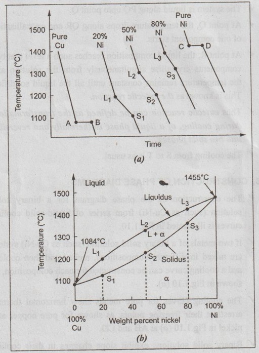
Construction Of Phase Diagram Using Cooling Curve

Digging Into Phase Diagrams Cooling Curves Physical Chemistry Using cooling curves to construct phase diagrams. the cooling curve method is one of the oldest and simplest methods to determine phase diagrams and phase transition temperatures. this is achieved by recording temperature (t) of a material versus time as it cools from its molten state through solidification (at constant pressure). What is cooling curve and how phase diagrams are constructed.

Practical Maintenance в Blog Archive в Phase Diagrams Part 1 By removing the time axis from the curves and replacing it with composition, the cooling curves indicate the temperatures of the solidus and liquidus for a given composition. this allows the solidus and liquidus to be plotted to produce the phase diagram: this page titled 12.5: interpretation of cooling curves is shared under a cc by nc sa. Phase diagram and “degrees of freedom”. phase diagrams is a type of graph used to show the equilibrium conditions between the thermodynamically distinct phases; or to show what phases are present in the material system at various t, p, and compositions. “equilibrium” is important: phase diagrams are determined by using slow cooling. One component phase diagram. figure 1 illustrates the temperatures and pressures at which water can exist as a solid, liquid or vapor. the curves represent the points at which two of the phases coexist in equilibrium. at the point tt vapor, liquid and solid coexist in equilibrium. in the fields of the diagram (phase fields) only one phase exists. A cooling curve for a sample that begins at the temperature and composition given by point a is shown in figure 8.10.1b 8.10. 1 b. figure 8.10.1 8.10. 1: (a) cooling of a two component system from liquid to solid. (b) cooresponding cooling curve for this process. as the sample cools from point a, the temperature will decrease at a rate.

Cooling Curves And Its Types Construction Of Phase Diagrams One component phase diagram. figure 1 illustrates the temperatures and pressures at which water can exist as a solid, liquid or vapor. the curves represent the points at which two of the phases coexist in equilibrium. at the point tt vapor, liquid and solid coexist in equilibrium. in the fields of the diagram (phase fields) only one phase exists. A cooling curve for a sample that begins at the temperature and composition given by point a is shown in figure 8.10.1b 8.10. 1 b. figure 8.10.1 8.10. 1: (a) cooling of a two component system from liquid to solid. (b) cooresponding cooling curve for this process. as the sample cools from point a, the temperature will decrease at a rate. If these curves are now straightened out, and the colours kept, with the white representing the solidification, it is possible to construct a basic phase diagram, as was shown for an isomorphous system in interpretation of cooling curves. this is shown below, where the white line is part of the phase diagram, constructed from the cooling curves, and the thin grey line is the actual phase. The construction of an eutectic phase diagram from cooling curves is depicted for the copper silver alloy system in figure 4. the pure metal compositions, a and f, and the eutectic, d, have cooling curves with a "thermal arrest" only, i.e. no other break in the curve.

Ppt Chapter 9 Phase Diagrams Powerpoint Presentation Free Download If these curves are now straightened out, and the colours kept, with the white representing the solidification, it is possible to construct a basic phase diagram, as was shown for an isomorphous system in interpretation of cooling curves. this is shown below, where the white line is part of the phase diagram, constructed from the cooling curves, and the thin grey line is the actual phase. The construction of an eutectic phase diagram from cooling curves is depicted for the copper silver alloy system in figure 4. the pure metal compositions, a and f, and the eutectic, d, have cooling curves with a "thermal arrest" only, i.e. no other break in the curve.

Comments are closed.