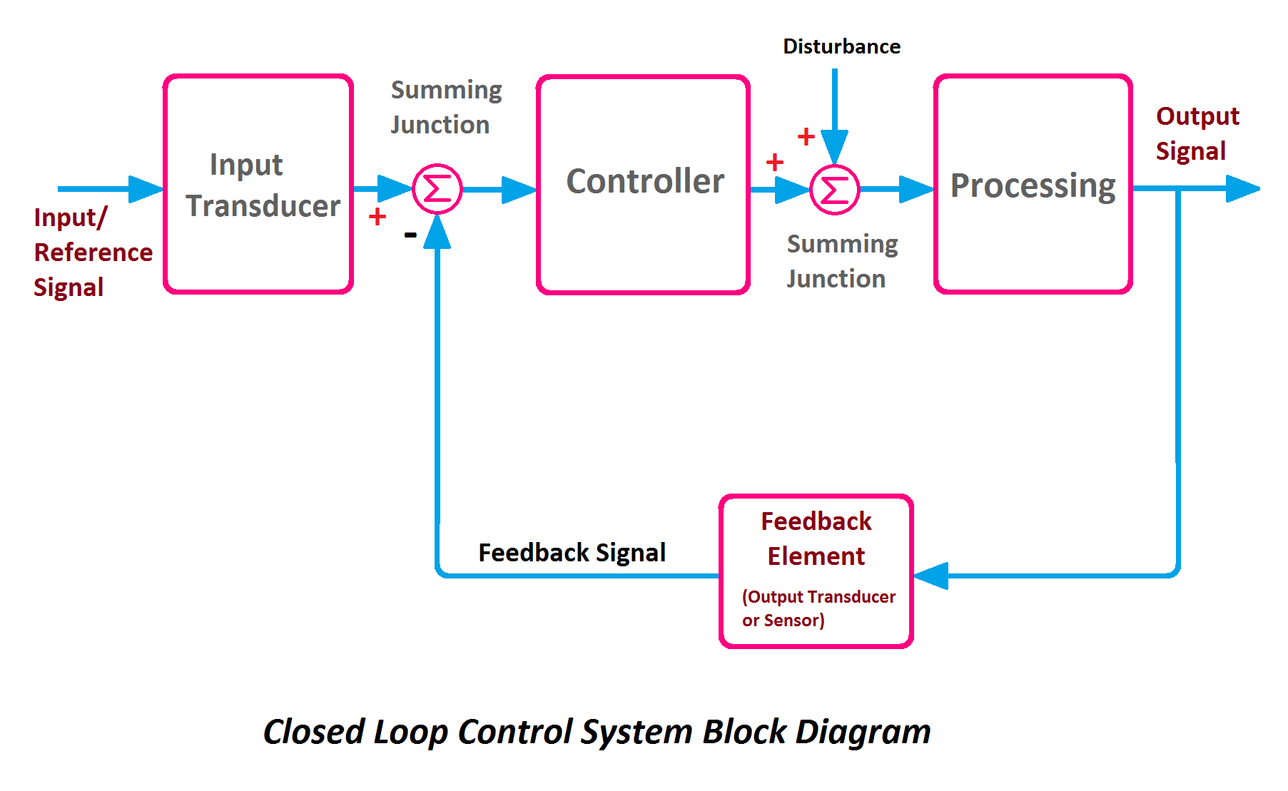
Closed Loop Control System Block Diagram Types Its Applications

Closed Loop Control System Block Diagram Types Its Applications Definition: a closed loop control system can be defined as, a system that has a feedback loop (or) a control system that uses a feedback signal to generate the output. the stability of this system can be controlled by a feedback system. so by providing a feedback system, any open loop control system can be changed into a closed loop. The primary objective of a closed loop control system is to enhance the system’s stability, accuracy, and overall performance. a simple example of a closed loop control system is a home thermostat. the thermostat can send a signal to the heater to turn it on or off. it uses a temperature sensor to detect the current air temperature.

Closed Loop Control System Block Diagram And Working Principle E The symbol used to represent a summing point in closed loop systems block diagram is that of a circle with two crossed lines as shown. the summing point can either add signals together in which a plus ( ) symbol is used showing the device to be a “summer” (used for positive feedback), or it can subtract signals from each other in which case a minus ( − ) symbol is used showing that the. Components of a control system. disregard the complexity of the system, it consists of an input (objective), the control system and its output (result). practically our day to day activities are affected by some type of control systems. there are two main branches of control systems: 1) open loop systems and 2) closed loop systems. control element. The thermostat heater is an example of closed loop control system. the thermostat senses the temperature of the system and maintains the temperature. input: desired temperature setpoint. output: actual temperature measured by the thermostat. plant: the heating system (heater) controller: the thermostat. Contents. 💡. key learnings: block diagram definition: a block diagram is defined as a diagram that represents each element of a control system with a block, symbolizing the transfer function of that element. transfer functions: each block’s transfer function represents the relationship between the input and output of that specific control.

Comments are closed.