Chinese 5 Pin Cdi Wiring Diagram Pictured Explained Off

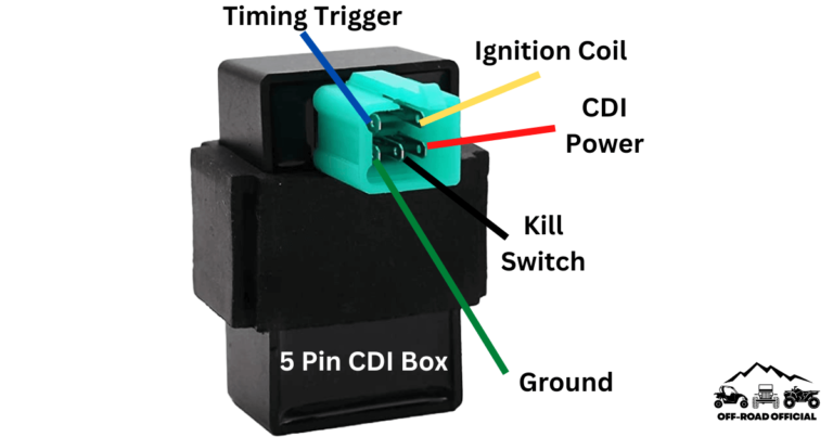
Chinese 5 Pin Cdi Wiring Diagram Pictured Explained Off Road Official The five pins are located inside of the connector and are responsible for providing power to the engine by linking the various parts of the ignition system together. these five pins connect the following components: timing trigger (or pulse generator) ignition coil. cdi ignition power. kill switch (or key switch). Step 1: unplug the stator connectors. step 2: remove the left engine cover step 3: disconnect the stator wires from the harness step 4: set multimeter to ohms mode. step 5: test resistance across each stator lead. readings vary widely by specific model and spec, but 1 ohm or less generally indicates a healthy stator.

Chinese 5 Pin Cdi Wiring Diagram Pictured Explained Off Road Official The 5 pin cdi box. the 5 pin cdi comes in the form of a black box, fitted with a male connector at the top. inside of this male connector, there are five different pins that connect to the various parts of the ignition system to provide power to the machine. these five pins connect the timing trigger pulse generator, ignition coil, ignition. The 5 pins on the cdi connector supply power, ground, and signals to control this process. here is a quick overview of each pin’s function: pin 1 – ground. pin 2 – 12vdc from battery via ignition switch and fuses. pin 3 – trigger signal from ac generator stator. pin 4 – switched 12vdc to ignition coil. On a 5 pin cdi system, you will find 5 different colored wires coming out of the cdi unit: green – connects to pickup coil signal input. white – connects to ac input from stator. red – main power source ( 12v from battery) black – main ground ( connection to battery) blue – output to ignition coil. There are two main variations of ac and dc cdi boxes used in polaris vehicles. most polaris models use a 6 pin cdi, but there are some older models that make use of a 5 pin cdi. either way, both types are very similar and should work in your polaris machine. 5 pin cdi box. the 5 pin cdi box is fitted with a male connector at the top.

5 Pin Cdi Wiring Diagram Pictured And Explained Off On a 5 pin cdi system, you will find 5 different colored wires coming out of the cdi unit: green – connects to pickup coil signal input. white – connects to ac input from stator. red – main power source ( 12v from battery) black – main ground ( connection to battery) blue – output to ignition coil. There are two main variations of ac and dc cdi boxes used in polaris vehicles. most polaris models use a 6 pin cdi, but there are some older models that make use of a 5 pin cdi. either way, both types are very similar and should work in your polaris machine. 5 pin cdi box. the 5 pin cdi box is fitted with a male connector at the top. The other major components in the chinese 5 wire cdi wiring diagram are the starter motor, the fuse box, the rectifier, the stator coil, the kill switch, and the ground connection. each component performs a specific task and must be connected correctly to ensure the system works properly. the starter motor connects the battery to the spark plug. The 5 pin cdi wiring diagram explained. a 5 pin cdi (capacitor discharge ignition) unit is an important component in the ignition system of many small engines, including motorcycles, dirt bikes, and atvs. it is responsible for generating the high voltage spark that ignites the fuel air mixture in the engine’s combustion chamber.

Chinese 5 Pin Cdi Wiring Diagram The other major components in the chinese 5 wire cdi wiring diagram are the starter motor, the fuse box, the rectifier, the stator coil, the kill switch, and the ground connection. each component performs a specific task and must be connected correctly to ensure the system works properly. the starter motor connects the battery to the spark plug. The 5 pin cdi wiring diagram explained. a 5 pin cdi (capacitor discharge ignition) unit is an important component in the ignition system of many small engines, including motorcycles, dirt bikes, and atvs. it is responsible for generating the high voltage spark that ignites the fuel air mixture in the engine’s combustion chamber.

Chinese 5 Pin Cdi Wiring Diagram

Comments are closed.