Automatic Led Control Using Ldr And Arduino

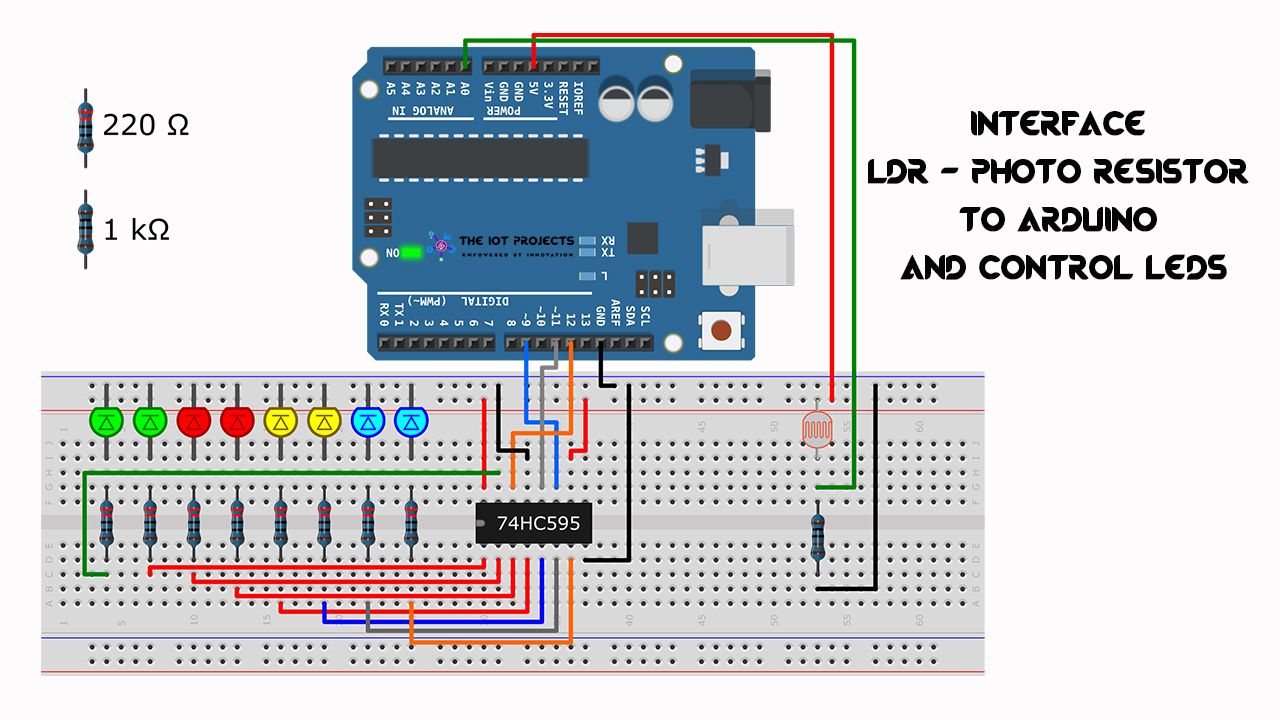
Automatic Led Control Using Ldr And Arduino Connect the 5v pin of the arduino to one of the ldr’s pins. connect the other pin of the ldr to a0 (analog pin of the arduino) and one pin of the 100kΩ resistor. connect the other pin of the 100kΩ resistor to the gnd (ground) of the arduino. attach a 220Ω resistor to the long leg ( ve) of the led on the breadboard. The ldr and led have been powered by arduino uno (board). it contains a code which uploaded to the board. and once it simulated you can see when ldr catches darkness it will send input to board and board will pass power to the led. we will use an blue led in this tutorial and we will need one ldr, to get readings.

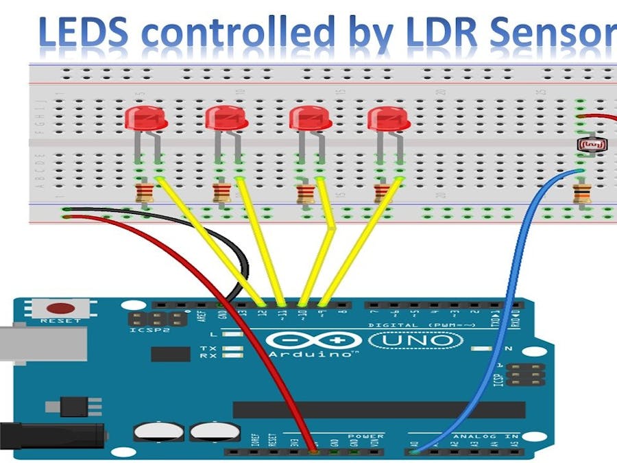
Automatic Led Control Using Ldr And Arduino 58 Off 1. arduino and ldr . the schematic is quite simple you should just follow the instructions bellow : 1.connect one of the ldr leg to the vcc (5v of the arduino). 2.connect the other ldr leg to the a4 pin of arduino and also to the resistor. 3.connect the (empty) resistor to the gnd of the arduino. note: you can see all the connections in the. Circuit diagram of ldr sensor and led with arduino. in the circuit, connect one leg of the ldr sensor to the 5v pin on arduino and the other leg to analog pin a0. then link one end of a resistor to a0 as well and connect its other end to ground. next, attach the cathode of an led through another resistor to ground and its anode to digital pin. Led part. 1. the green wire is attached to resistor's another leg. 2. the orange wire is attached to led short leg. ldr part. 1. the yellow wire is attach to ldr in the same resistor column. the blue wire is attached to resistor's empty leg and . 2. the red wire is attached to ldr another leg. power rail section: 1. The main components of the automatic room lights project are arduino, the ambient sensor and the relay module to control the lights. typically, the project entails assembling the hardware parts, such as the arduino board, the photoresistor sensor, and the leds or other lighting fixtures. using the arduino ide, the system is programmed with code.

Arduino Tutorial Controlling Leds With Ldr Sensor Arduino Project Hub Led part. 1. the green wire is attached to resistor's another leg. 2. the orange wire is attached to led short leg. ldr part. 1. the yellow wire is attach to ldr in the same resistor column. the blue wire is attached to resistor's empty leg and . 2. the red wire is attached to ldr another leg. power rail section: 1. The main components of the automatic room lights project are arduino, the ambient sensor and the relay module to control the lights. typically, the project entails assembling the hardware parts, such as the arduino board, the photoresistor sensor, and the leds or other lighting fixtures. using the arduino ide, the system is programmed with code. Step 1: understanding ldr and pwm pins of arduino. there are many awesome references to understand the working of pwm pins of ardunio . in simple terms the pwm refers to the pulse with modulation feature of the arduino. in the pwm pins the output signal via a pwm pin will be an analog signal ( at least it behaves like one) acquired as a digital. An ldr (l ight d ependent r esistor) is an electronic device that is being used for light intensity sensing applications. the ldr has a relatively low resistance in light, and when the surrounding gets darker the ldr’s resistance significantly increases. we typically use ldr with arduino as a light sensor to sense the ambient light intensity.

Comments are closed.