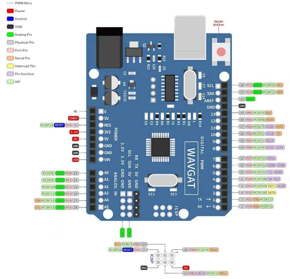
Arduino Uno R3 Diagram

Arduino Uno R3 Labelled Diagram Arduino uno is a microcontroller board based on the atmega328p.it has 14 digital input output pins (of which 6 can be used as pwm outputs), 6 analog inputs, a 16 mhz ceramic resonator, a usb connection, a power jack, an icsp header and a reset button. 1 reset. 10 xtal2. 9 xtal1. 21 aref 20 avcc 22 agnd. 7 vcc 8 gnd. (sck)pb5 19 (miso)pb4 18 (mosi)pb3 17 (ss)pb2 16 (oc1)pb1 15 (icp)pb0 14. (adc5)pc5 28 (adc4)pc4 27 (adc3)pc3 26 (adc2)pc2 25 (adc1)pc1 24 (adc0)pc0) 23. (ain1)pd7 13 (ain0)pd6 12 (t1)pd5 11 (t0)pd4 6 (int1)pd3 5 (int0)pd2 4 (txd)pd1 3 (rxd)pd0 2.

Schematic Diagram Of Arduino Uno R3 Wiring Diagram The arduino uno r3 board includes the following specifications. it is an atmega328p based microcontroller. the operating voltage of the arduino is 5v. the recommended input voltage ranges from 7v to 12v. the i p voltage (limit) is 6v to 20v. digital input and output pins 14. digital input & output pins (pwm) 6. Tm uno reference design. reference designs are provided "as is" and "with all faults". arduino disclaims all other warranties, express or implied, regarding products, including but not limited to, any implied warranties of merchantability or fitness for a particular purpose. arduino may make changes to specifications and product descriptions at. The arduino uno r3 pinout is a reference diagram that shows the layout and function of each pin on the arduino uno r3 board. it is essential for understanding how to connect and interact with various components and peripherals on the board. the arduino uno r3 pinout consists of a total of 20 digital input output pins, 6 analog input pins, a. The arduino uno. starting clockwise from the top center: analog reference pin (orange) digital ground (light green) digital pins 2 13 (green) digital pins 0 1 serial in out tx rx (dark green) these pins cannot be used for digital i o (digitalread and digitalwrite) if you are also using serial communication (e.g. serial.begin).

Pin Configuration Of Arduino Uno R3 The arduino uno r3 pinout is a reference diagram that shows the layout and function of each pin on the arduino uno r3 board. it is essential for understanding how to connect and interact with various components and peripherals on the board. the arduino uno r3 pinout consists of a total of 20 digital input output pins, 6 analog input pins, a. The arduino uno. starting clockwise from the top center: analog reference pin (orange) digital ground (light green) digital pins 2 13 (green) digital pins 0 1 serial in out tx rx (dark green) these pins cannot be used for digital i o (digitalread and digitalwrite) if you are also using serial communication (e.g. serial.begin). Overall, the schematic diagram is a vital resource for anyone looking to understand and work with the arduino uno r3. it provides a detailed representation of the electrical connections and component values, allowing you to gain a deeper understanding of the board’s functionality and make informed decisions when working with it. Download this manual. arduino® uno r3. product reference manual. sku: a000066. description. the arduino uno r3 is the perfect board to get familiar with electronics and coding. this versatile microcontroller. is equipped with the well known atmega328p and the atmega 16u2 processor. this board will give you a great first experience within the.

Comments are closed.