Arduino To 16 2 Lcd Display Proteus Arduino Proteus Simulation

Arduino To 16 2 Lcd Display Proteus Arduino Proteus This commands in arduino can be provided using the codes. lcd stands for liquid crystal display. 16×2 lcd is named so because; it has 16 columns and 2 rows. there are a lot of combinations available like 8×1, 8×2, 10×2, 16×1, etc. but the most used one is the 16×2 lcd. so, it will have 16×2 = 32 characters in total and each character. The correct way to simulate it btw is to add a pcf 8574 beween your arduino and the lcd. pins 4,5,6 of the 8574 go to rs, rw, e of the lcd, while p4 to p7 connect to the lcd d4 to d7. a0, a1, a2 in my case are grounded (this give address 0x20 in sim not in real life) the i2c address of the 8574 on proteus is 0x20.

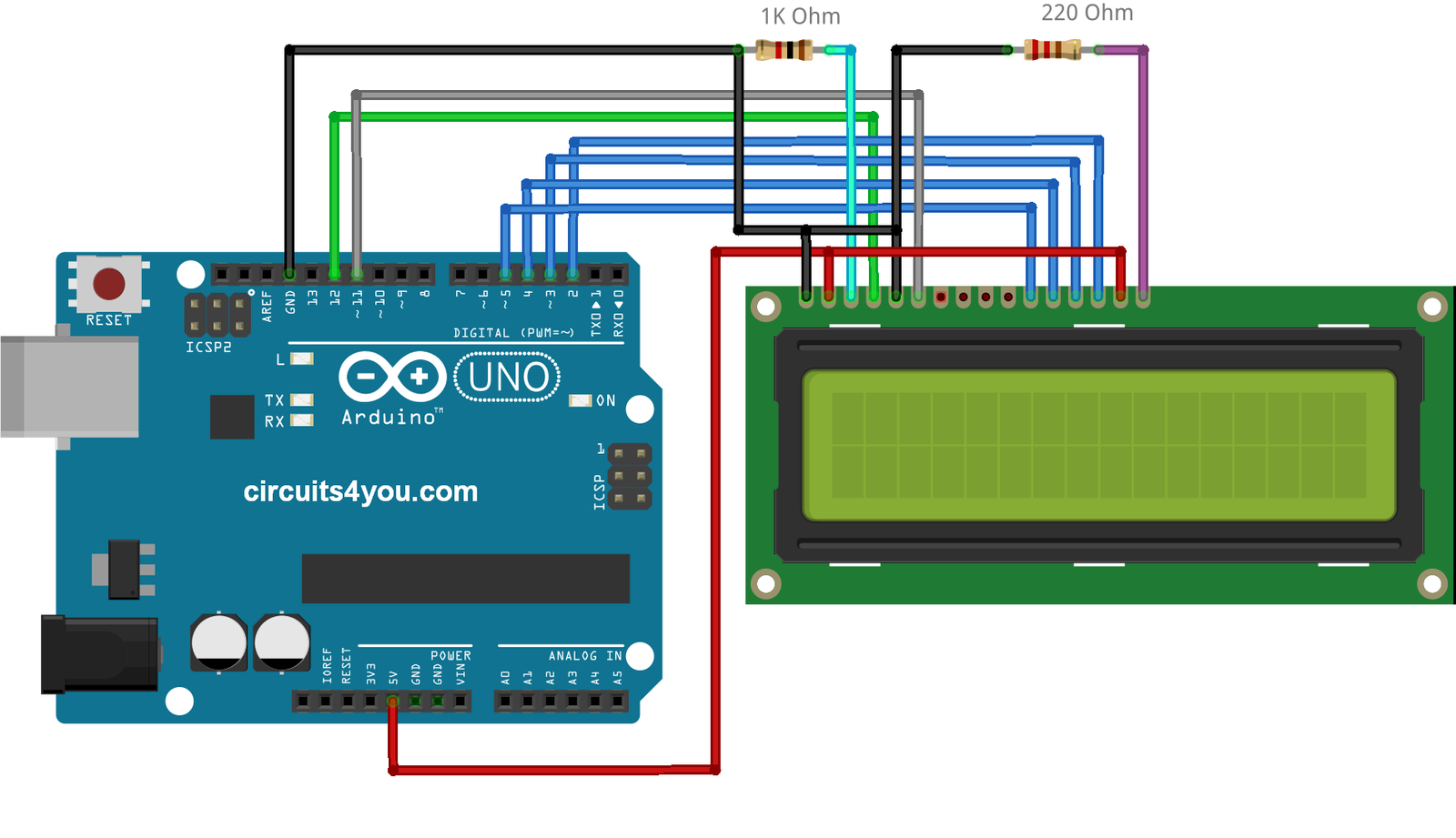
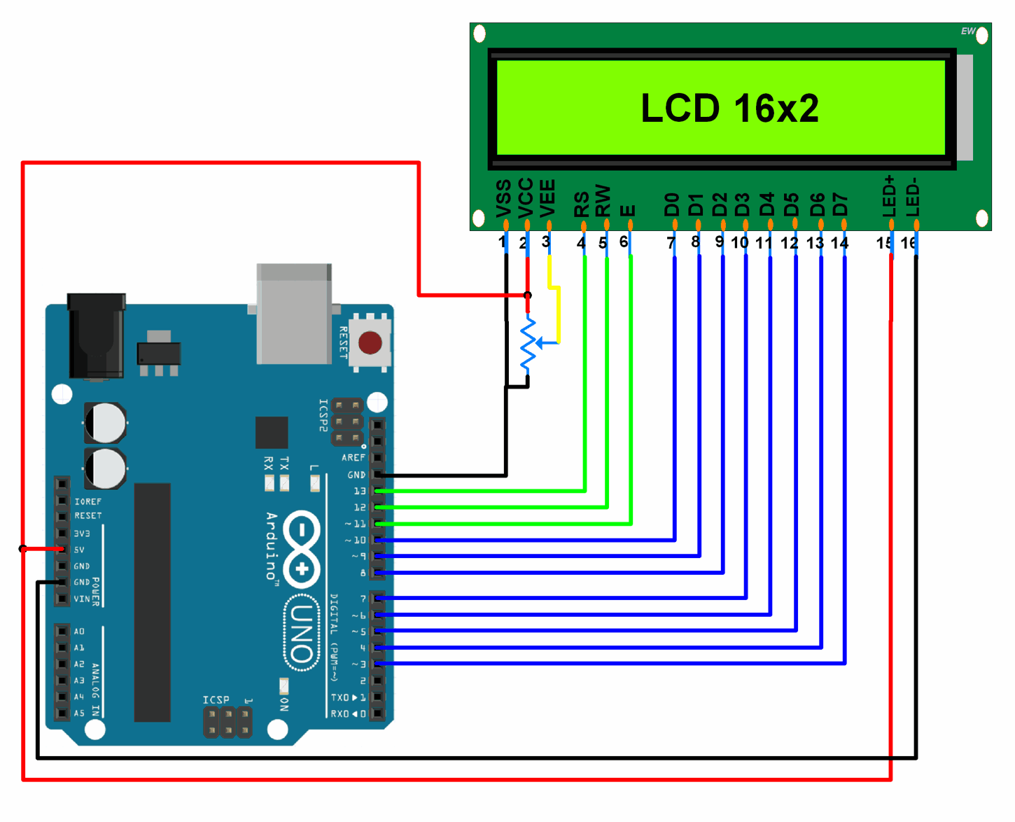
16г 2 Lcd Interface With Arduino Uno Circuits4you Arduino robotic online individual classes (via skype) with practical explanations, contact me on: nik261190@gmail print "hello world"in 16x2 lcd display u. 16×2 lcd: lcd stands for liquid crystal display. 16×2 lcd is named so because; it has 16 columns and 2 rows. there are a lot of combinations available like 8×1, 8×2, 10×2, 16×1, etc. but the most used one is the 16×2 lcd. so, it will have 16×2 = 32 characters in total and each character will be made of 5×8 pixel dots. 16x2 lcd module pinout. the 16x2 has a 16 pin connector. the module can be used either in 4 bit mode or in 8 bit mode. in 4 bit mode, 4 of the data pins are not used and in 8 bit mode, all the pins are used. and the connections are as follows: and here are the pins and corresponding functions. ground ground (0v). This video is demonstrated simulation on proteus of i2c lcd16x2 with arduino step by step. #voidlooprobotech #i2clcd16x2 #vlrobotech #proteus #arduino simul.

Proteus I2c Interfacing Arduino With Ssd1306 Oled Display Simple 16x2 lcd module pinout. the 16x2 has a 16 pin connector. the module can be used either in 4 bit mode or in 8 bit mode. in 4 bit mode, 4 of the data pins are not used and in 8 bit mode, all the pins are used. and the connections are as follows: and here are the pins and corresponding functions. ground ground (0v). This video is demonstrated simulation on proteus of i2c lcd16x2 with arduino step by step. #voidlooprobotech #i2clcd16x2 #vlrobotech #proteus #arduino simul. #engineeringonline #proteus #16x2lcdthis video explains how to interface a 16*2 lcd with arduino in porteus simulatorinterfacing of 16x2 lcd with arduino:htt. Now double click the arduino in proteus isis and properties window will pop up. in properties panel, under the program file section, browse to arduino hex file as shown in below figure and upload it. now click ok and run your simulation, if everything goes fine then your lcd will start showing the characters as shown in below figure: you should.

Lcd Display Schematic Diagram #engineeringonline #proteus #16x2lcdthis video explains how to interface a 16*2 lcd with arduino in porteus simulatorinterfacing of 16x2 lcd with arduino:htt. Now double click the arduino in proteus isis and properties window will pop up. in properties panel, under the program file section, browse to arduino hex file as shown in below figure and upload it. now click ok and run your simulation, if everything goes fine then your lcd will start showing the characters as shown in below figure: you should.

Comments are closed.