Arduino Project 4 Ldr And Buzzer Experiment Buildcircuit Com

Arduino Project 4 Ldr And Buzzer Experiment Buildcircuit Com The output of this experiment is sound with different frequencies that are produced depending upon the light falling on the ldr photoresistor. steps. – connect the negative black wire of the buzzer to pin ground and the black positive to the digital pin 9. – connect to pin 5v a resistor of 1 kΩ and the other end of it a photoresistor and. Dark light sensor using transistor. automatic dark detector senses darkness. as the light level decreases and ldr meets the maximum threshold resistance, the circuit automatically switches on the led d1. dark sensor with variable resistor: a dark detector can be made using a variable resistor. the sensitivity of the circuit can be adjusted with.

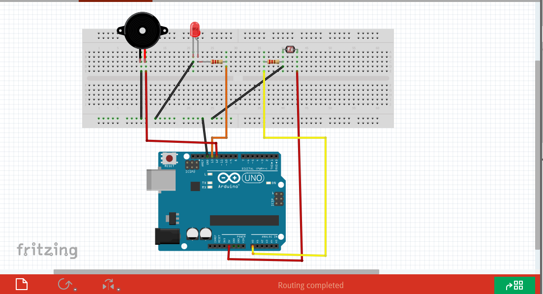
An Experiment With Ldr And Arduino Buildcircuit Electronics Step 3: arduino connection. the wire connect to ground, then the same wire attach to board. the wire connect to buzzer short leg, then the same wire attach to gnd on the board. the wire attach to led short leg, then the same wire connect to gnd on the board. the wire connect to 10k resistor empty leg, then the same wire connect to gnd on the board. Circuit connection. place the ldr resistor and buzzer on the breadboard and connect the positive pin of the buzzer to pin 9 of arduino and the gnd pin of the buzzer is connected to the gnd of arduino. connect a 10k resistor to the 5v pin of the arduino and to it the ldr and a cable that leads to pin a0. connect the arduino gnd pin to the other. An ldr (l ight d ependent r esistor) is an electronic device that is being used for light intensity sensing applications. the ldr has a relatively low resistance in light, and when the surrounding gets darker the ldr’s resistance significantly increases. we typically use ldr with arduino as a light sensor to sense the ambient light intensity. After connecting the ldr to your arduino, you can check for the values coming from the ldr via the arduino. to do this, connect the arduino via usb to your pc and open up the arduino ide or software. next, paste this code and upload it to your arduino: int sensorpin = a0; select the input pin for ldr. int sensorvalue = 0; variable to.

Active Buzzer With Ldr And Led Arduino An ldr (l ight d ependent r esistor) is an electronic device that is being used for light intensity sensing applications. the ldr has a relatively low resistance in light, and when the surrounding gets darker the ldr’s resistance significantly increases. we typically use ldr with arduino as a light sensor to sense the ambient light intensity. After connecting the ldr to your arduino, you can check for the values coming from the ldr via the arduino. to do this, connect the arduino via usb to your pc and open up the arduino ide or software. next, paste this code and upload it to your arduino: int sensorpin = a0; select the input pin for ldr. int sensorvalue = 0; variable to. The ldr light sensor module is capable of detecting and measuring light in the surrounding environment. the module provides two outputs: a digital output (low high) and an analog output. in this tutorial, we will learn how to use an arduino and an ldr light sensor module to detect and measure the light level. Circuit diagram of ldr sensor and led with arduino. in the circuit, connect one leg of the ldr sensor to the 5v pin on arduino and the other leg to analog pin a0. then link one end of a resistor to a0 as well and connect its other end to ground. next, attach the cathode of an led through another resistor to ground and its anode to digital pin.

Comments are closed.