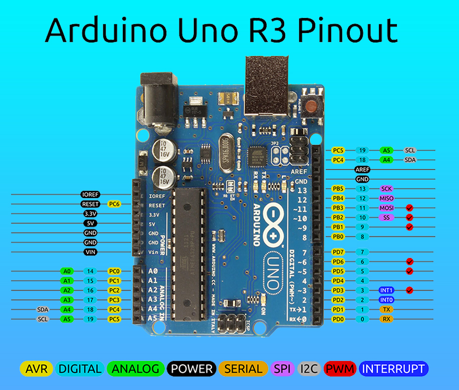
Arduino Pins Configuration Arduino Pins Explained In Hindi Arduinoо

Arduino Uno Pinout Diagram And Pin Configuration Explained Etechnog Our online store : store.gsmclinic our online store : store.gsmclinic buy arduino uno r3 with cable : bit.ly 3edtkxubuy ardui. Arduino uno has a couple of other pins as explained below: aref: used to provide reference voltage for analog inputs with analogreference() function. reset pin: making this pin low, resets the microcontroller. communication . arduino can be used to communicate with a computer, another arduino board or other microcontrollers.
Explain Pin Configuration Of Arduino Uno External interrupt pins: this pin of the arduino board is used to produce the external interrupt and it is done by pin numbers 2 and 3. pwm pins: this pins of the board is used to convert the digital signal into an analog by varying the width of the pulse. the pin numbers 3,5,6,9,10 and 11 are used as a pwm pin. Arduino uno pinout digital pins. pins 0 13 of the arduino uno serve as digital input output pins. pin 13 of the arduino uno is connected to the built in led. in the arduino uno pins 3,5,6,9,10,11 have pwm capability. it’s important to note that: each pin can provide sink up to 40 ma max. but the recommended current is 20 ma. Arduino uno pinout – diagram . arduino uno pin description. the pin wise description of arduino uno pins is explained below: digital pins (d0 d13) these pins can be used for both digital input and output and operate at 5 volts. pins d0 to d13 are digital pins, and each can be configured as input or output. The arduino uno board has over 20 pins that you can use for various applications. in this tutorial, we’ll explore the arduino uno pinout and break down each section of arduino pins to discuss its functionality and use in detail. you’ll learn how to use arduino pins in your project and get a solid understanding of a lot of arduino fundamentals.

Arduino Pin Configuration For Arduino Uno R3 Microcontroler Arduino uno pinout – diagram . arduino uno pin description. the pin wise description of arduino uno pins is explained below: digital pins (d0 d13) these pins can be used for both digital input and output and operate at 5 volts. pins d0 to d13 are digital pins, and each can be configured as input or output. The arduino uno board has over 20 pins that you can use for various applications. in this tutorial, we’ll explore the arduino uno pinout and break down each section of arduino pins to discuss its functionality and use in detail. you’ll learn how to use arduino pins in your project and get a solid understanding of a lot of arduino fundamentals. The arduino uno pins compatible with pwm are the pins 3, 5, 6, 9, 10 and 11. so you have 6 pins where you can create a pwm, using the analogwrite () function. this can be quite useful to control some actuators that require a fine voltage tuning, and are not only switched on or off. 3. pwm (pulse width modulation) pins: definition: pwm pins are a subset of digital pins capable of simulating analog output by rapidly switching between high and low states to control the average voltage. numbering: pwm pins are often marked with a tilde symbol (~) next to their digital pin numbers (e.g., ~d3, ~d9).

Comments are closed.