Analog Input To Servo Motor Using Arduino Theorycircuit Do It

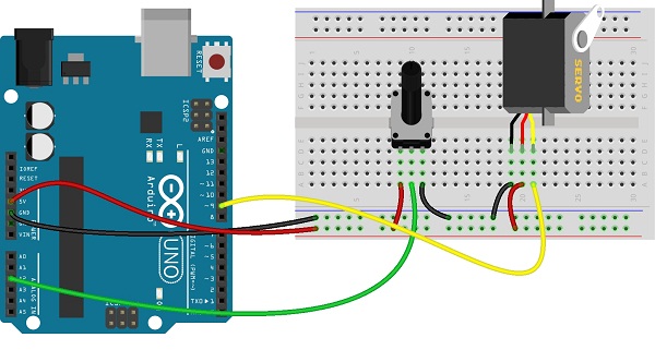
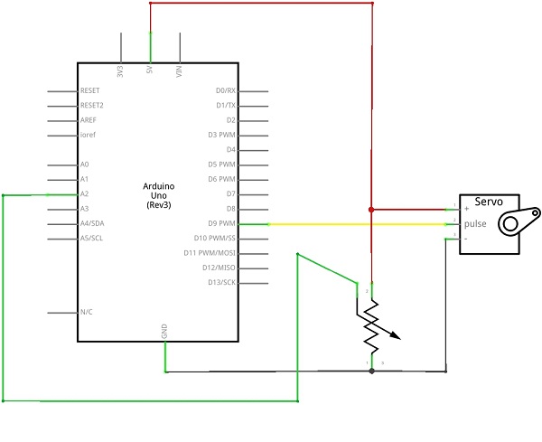
Analog Input To Servo Motor Using Arduino Theorycircuit Do It The servo motors are used in many applications, this motor works with input pulse and rotation depends on input pulse duration. here the rotation of variable resistor imitate by the rotation of servo motor. (a servo is a rotary actuator) in this project variable resistor connected with analog input pin a0 and the servo motor pulse pin connected. As you see with respect to pwm signal (high), servo motor shaft rotates with precise angle, by coding and using sensor we can drive many possible applications. some examples from theorycircuit . 1. simple automatic arduino pet feeder. 2. analog input to servo motor using arduino. 3. servo motor driver circuit.

Analog Input To Servo Motor Using Arduino Theorycircuit Do It System september 14, 2017, 6:35pm 1. how to use servo motor from analog pins in arduino uno. as all my pwm pins are used up. by thecway i have digital pin 8 and 13 left also. i am using arduino uno. i heard that we csn use analog pins as pwm by some library. if so please tell how to use it in detail. other suggestions are also welcomed. The flex sensor can be used for servo motor control, intensity control or you can use where ever the resistance need to be changed when the bending occurs. here the circuit constructed with arduino and led, when the flex sensor bends the intensity of led changes accordingly. circuit diagram. here the led connected with pwm output pin of arduino. Servo motors are controlled by sending a pwm (pulse width modulation) signal to the signal line of the servo. the width of the pulses determines the position of the output shaft. when you send the servo a signal with a pulse width of 1.5 milliseconds (ms), the servo will move to the neutral position (90 degrees). Connect the brown or black wire (gnd) of the servo motor to the gnd pin on the arduino. connect the orange or yellow wire (signal) of the servo motor to a digital pwm pin on the arduino. connect the positive end of potentiometer to 3.3v pin of arduino. connect the gnd end to the gnd pin of arduino.

Arduino Servo Motor Control Tutorial With Circuit Diagram And Code Servo motors are controlled by sending a pwm (pulse width modulation) signal to the signal line of the servo. the width of the pulses determines the position of the output shaft. when you send the servo a signal with a pulse width of 1.5 milliseconds (ms), the servo will move to the neutral position (90 degrees). Connect the brown or black wire (gnd) of the servo motor to the gnd pin on the arduino. connect the orange or yellow wire (signal) of the servo motor to a digital pwm pin on the arduino. connect the positive end of potentiometer to 3.3v pin of arduino. connect the gnd end to the gnd pin of arduino. First, to test that the servo motor is working, upload the following test code. once uploaded, the servo motor should start moving back and forth between 0 and 180 degrees. make sure your servo is connected to pin 9 as shown in the circuit diagram. myservo.attach(9); attaches the servo on pin 9 to the servo object. How to use a 360 degree servo with arduino. step 1: arduino ide installation. step 2: installing necessary libraries. step 3: wiring the 360 degree servo motor with arduino uno. step 4: setting up the arduino for uploading the code. step 5: sample code for testing the servo. observations.

How To Control Servo Motor With Arduino Full Explanation With Code And First, to test that the servo motor is working, upload the following test code. once uploaded, the servo motor should start moving back and forth between 0 and 180 degrees. make sure your servo is connected to pin 9 as shown in the circuit diagram. myservo.attach(9); attaches the servo on pin 9 to the servo object. How to use a 360 degree servo with arduino. step 1: arduino ide installation. step 2: installing necessary libraries. step 3: wiring the 360 degree servo motor with arduino uno. step 4: setting up the arduino for uploading the code. step 5: sample code for testing the servo. observations.

Comments are closed.