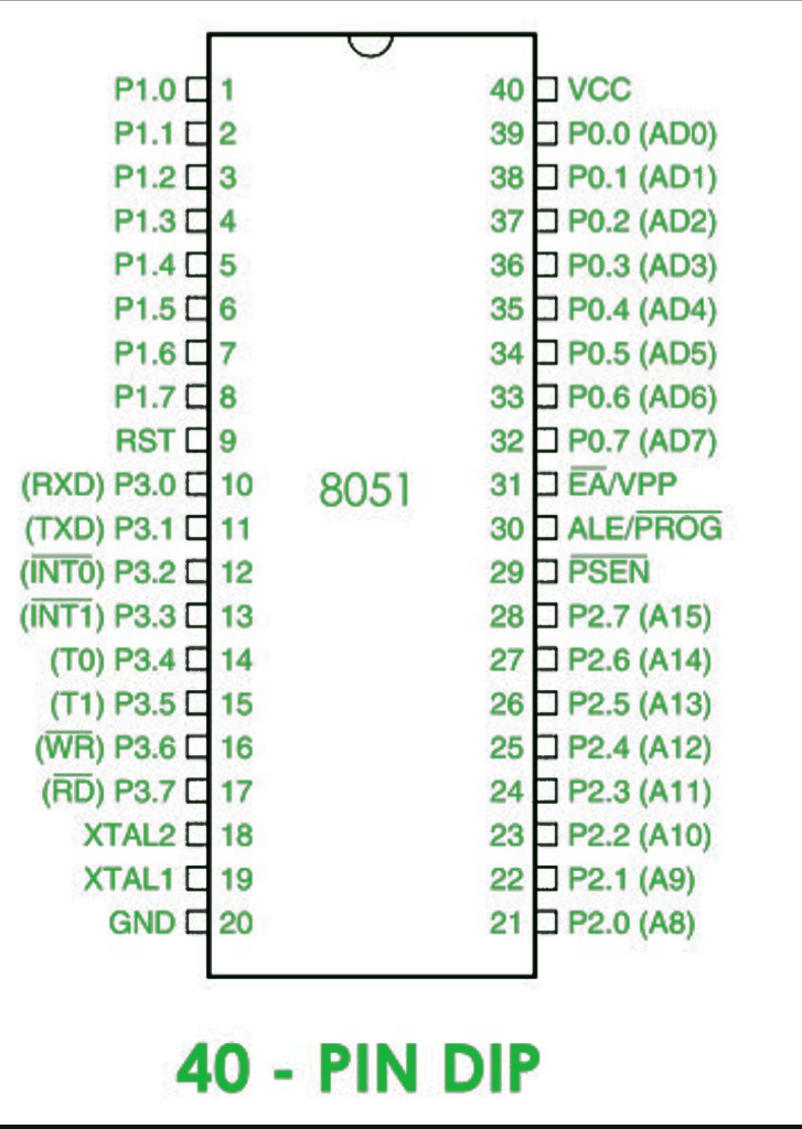
8051 Microcontroller Pin Diagram 8051 Microcontroller

Pin Diagram Of 8051 8051 Microcontroller Course The 8051 microcontroller is a popular 8 bit microcontroller widely used in embedded systems. it is a single chip microcontroller with a harvard architecture that includes a cpu, ram, rom, and several peripherals. the 8051 microcontroller has a 40 pin dual in line package (dip) that provides various inputs and outputs for communication with. The pin diagram of 8051 microcontroller looks as follows −. pins 1 to 8 − these pins are known as port 1. this port doesn’t serve any other functions. it is internally pulled up, bi directional i o port. pin 9 − it is a reset pin, which is used to reset the microcontroller to its initial values. pins 10 to 17 − these pins are known as.

Pin Diagram Of 8051 Microcontroller Geeksforgeeks The pin description or pin configuration of the 8051 microcontroller will describe the functions of each pins of the 8051 microcontroller. let us now see the pin description. pins 1 – 8 (port 1): pins 1 to 8 are the port 1 pins of 8051. port 1 pins consists of 8 – bit bidirectional input output port with internal pull – up resistors. It is active high pin. it is used to reset. if we apply active high signal to this pin, 8051 microcontroller will reset and turn off all its functions. it will erase all values of registers and it will make all program counter values to zero. figure below shows the power on reset circuitry. The general schematic diagram of 8051 microcontroller is shown above. we can see 3 system inputs, 3 control signals and 4 ports (for external interfacing). a vcc power supply and ground is also shown. now lets explain and go through each in detail. system inputs are necessary to make the micro controller functional. Therefore, the microcontroller 8051’s pin diagram and explanation is given below. port1 (pin1 to pin8): port1 includes pin1.0 to pin1.7 and these pins can be configured as input or output pins. pin 9 (rst): reset pin is used to reset 8051 microcontroller by giving a positive pulse to this pin. port3 (pin 10 to 17): the port3 pins are similar.

Comments are closed.