8 Bit Binary To 7 Segment Display Images And Photos Finder

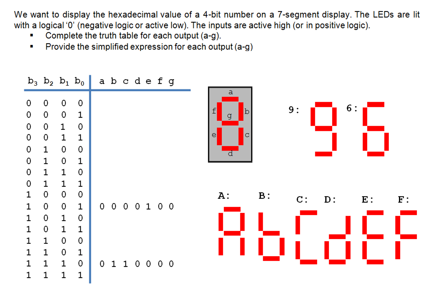
8 Bit Binary To 7 Segment Display Images And Photos Finder A binary coded decimal (bcd) to 7 segment display decoder such as the ttl 74ls47 or 74ls48, have 4 bcd inputs and 7 output lines, one for each led segment. this allows a smaller 4 bit binary number (half a byte) to be used to display all the denary numbers from 0 to 9 and by adding two displays together, a full range of numbers from 00 to 99. The display consists of seven segments identified by a letter (from a to g), organized as follows: and each segment is generally associated with an lcd screen or a led and can thus be activated on 1 or off 0. there are a total of 128 possible combinations of display, although it is most often the combinations for the 10 digits (from 0 to 9.

Binary To 7 Segment Decoder Youtube The outputs to these feed into individual 7447 bcd to 7 segment decoder chips, which then go to a 3 digit common anode 7 segment display. i'm using a 555 timer for my clock, the nominal frequency is 4.8 hz (at the moment) which i plan to kick up to about 200 khz once everything is working. The complete verilog code for seven segment display for common anode (led will glow if we give logic 0 to the segment) is given below. if you have common anode just change 0 to 1 and 1 to 0. also, make sure to check logic 0 is for enable or logic 1 is for disable the seven segment display. the board i am using has active low enabled display. Getting them to display correctly on the 7 segment displays is the tricky part. you see, i'm also told that i must use two 74x49's (immediately before the two 7 segment displays) that translate a 4 bit binary number that then causes the correct segments of the display to light up. for example, 0000 displays 0, 0001 displays 1, 0010 displays 2, etc. A seven segment counter display consists of an integrated circuit (ic) 555 timer, a cd4033 4 bit binary counter, and a 7 segment display. the ic 555 timer functions as the trigger for the counter, while the cd4033 is responsible for counting and incrementing the counts. it then sends the output values to the 7 segment display, which shows the.

Seven Segment Display Specification Getting them to display correctly on the 7 segment displays is the tricky part. you see, i'm also told that i must use two 74x49's (immediately before the two 7 segment displays) that translate a 4 bit binary number that then causes the correct segments of the display to light up. for example, 0000 displays 0, 0001 displays 1, 0010 displays 2, etc. A seven segment counter display consists of an integrated circuit (ic) 555 timer, a cd4033 4 bit binary counter, and a 7 segment display. the ic 555 timer functions as the trigger for the counter, while the cd4033 is responsible for counting and incrementing the counts. it then sends the output values to the 7 segment display, which shows the. The cd4511 is a combination counter, decoder and 7 segment driver in one chip, and it is not as voltage specific as the ttl 74xxx series. i don't understand what you mean by 8 10 and 14 bit numbers. in binary, 8 bits represents the number 256, 10 is the number 1024 and 14 bits translates to the number 16284 (xsub2). perhaps you could clarify. The first device (i'm not even sure what device) recieves a binary signal that counts up and displays on the first 7 sgment display (indicating 'ones' unit). it operates normally until it hits 1010 (10). then it needs to (a) reset and count again, and (b) send a carry of '1' to the next device (that presumably gets added to it's own binary count).

Logisim Simulation 4 4 Bit Binary To 7 Segment Display Using A 4x16 The cd4511 is a combination counter, decoder and 7 segment driver in one chip, and it is not as voltage specific as the ttl 74xxx series. i don't understand what you mean by 8 10 and 14 bit numbers. in binary, 8 bits represents the number 256, 10 is the number 1024 and 14 bits translates to the number 16284 (xsub2). perhaps you could clarify. The first device (i'm not even sure what device) recieves a binary signal that counts up and displays on the first 7 sgment display (indicating 'ones' unit). it operates normally until it hits 1010 (10). then it needs to (a) reset and count again, and (b) send a carry of '1' to the next device (that presumably gets added to it's own binary count).
.jpg)
Seven Segment Display Encoder

Comments are closed.