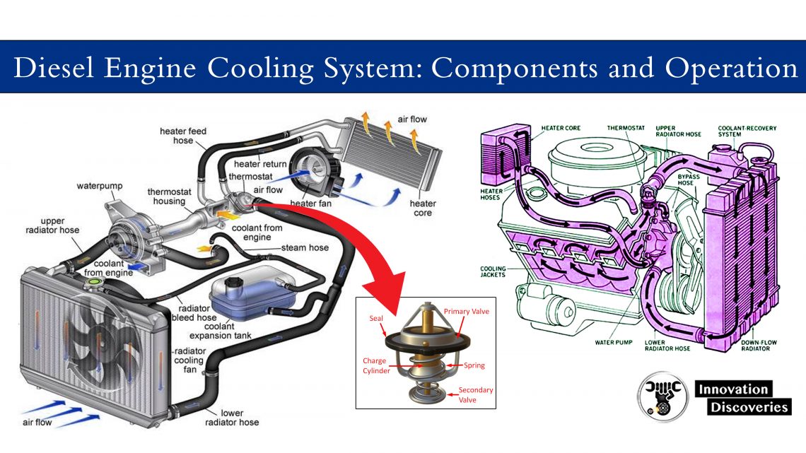
6 5 Turbo Diesel Cooling System Diagram

6 5 Diesel Engine Diagram Cooling system in a 6.5 turbo diesel engine diagram. the cooling system in a 6.5 turbo diesel engine is crucial for maintaining optimal engine temperature and preventing overheating. it consists of several components that work together to regulate the engine’s temperature and ensure smooth operation. let’s take a closer look at each of. He can coat just about anything you need. so there you have it! positive proof that the champion cooling systems aluminum radiator, along with the standard cooling upgrades can give you maximum cooling for your 6.5 turbo diesel. i suggest you give john a shout and get yours today and then follow along with the install here!.

Diesel Engine Cooling System Components And Operation That system worked well with the 6.2l series, of low thermal output, but the '93 '96 6.5l turbomotor soon revealed the system shortcomings, by overheating rapidly under load. the '97 coolant system upgrade consists of revised head coolant passages for the indirect injection combuston chamber and valves, new dual t stat housing without bypass blockoff, dual robertshaw hi flow t stats, and. 3 8" id from tank to lift pump, from lift pump to fuel filter manager. 1 4" id from fuel filter manager to injection pump and t valve drain. 5 16" id for the return line back to fuel tank. 3.5mm injector return line. fuel tank sock the fuel tank sock provides the first level of filtering to the fuel system. Engines warms to 180* first stage of the primary t stat allowing some flow to the radiator. at 185* secondary t stat starts to open flowing more to the radiator. in here @ arond 132* the turbo starts recieveing coolant through a thermo controlled circuit by pass. at 203* the primary stat is full open. There are two right in front and two mid way down on either side. this is where the long extensions come in handy. once it's loose, pull the shroud up and out. remove the last 10mm bolt on each bracket securing the radiator down. on the passenger side, remove the lower radiator hose, heater hose, overflow hose, and low coolant connector.

Schematic Diagram Of Engine Cooling System Engines warms to 180* first stage of the primary t stat allowing some flow to the radiator. at 185* secondary t stat starts to open flowing more to the radiator. in here @ arond 132* the turbo starts recieveing coolant through a thermo controlled circuit by pass. at 203* the primary stat is full open. There are two right in front and two mid way down on either side. this is where the long extensions come in handy. once it's loose, pull the shroud up and out. remove the last 10mm bolt on each bracket securing the radiator down. on the passenger side, remove the lower radiator hose, heater hose, overflow hose, and low coolant connector. The 6.5l detroit diesel wasn’t the most reliable engine — they were known to experience injection pump failure, broken camshaft and overheat. regardless of the known issues associated with these engines, the earlier 1992 and 93 model years were still the best in terms of performance and reliability. these pre 1994 engines had stronger. Balanced flow water pump for 6.5 diesel. a straight swap to a 2000 pump, part #251 603 not only bumps the stock flow from 97 gallons per minute to 127 gpm, but also brings it to an almost 50 50 flow balance. you can see where that would greatly improve cooling. couple that with a hayden 2886 fan clutch and a 21” duramax fan and you’ve.

Comments are closed.