555 Ic Inverter Circuit Diagram

Ic 555 Inverter Circuit Diagram вђ Diy Electronics Projects 5 application. in this tutorial, we are going to make an “inverter circuit using ic 555 “. an inverter is nothing but a dc to ac converter ( a power electronic device or circuitry that changes direct current (dc) to alternating current (ac). the resulting ac frequency obtained depends on the particular device employed). The diagram above shows the entire design of the proposed spwm inverter circuit using ic 555, where the center ic 555 and the associated bjt mosfet stages forms a basic square wave inverter circuit. our aim is to chop these 50hz square waves into the required spwm waveform using an opamp based circuit.

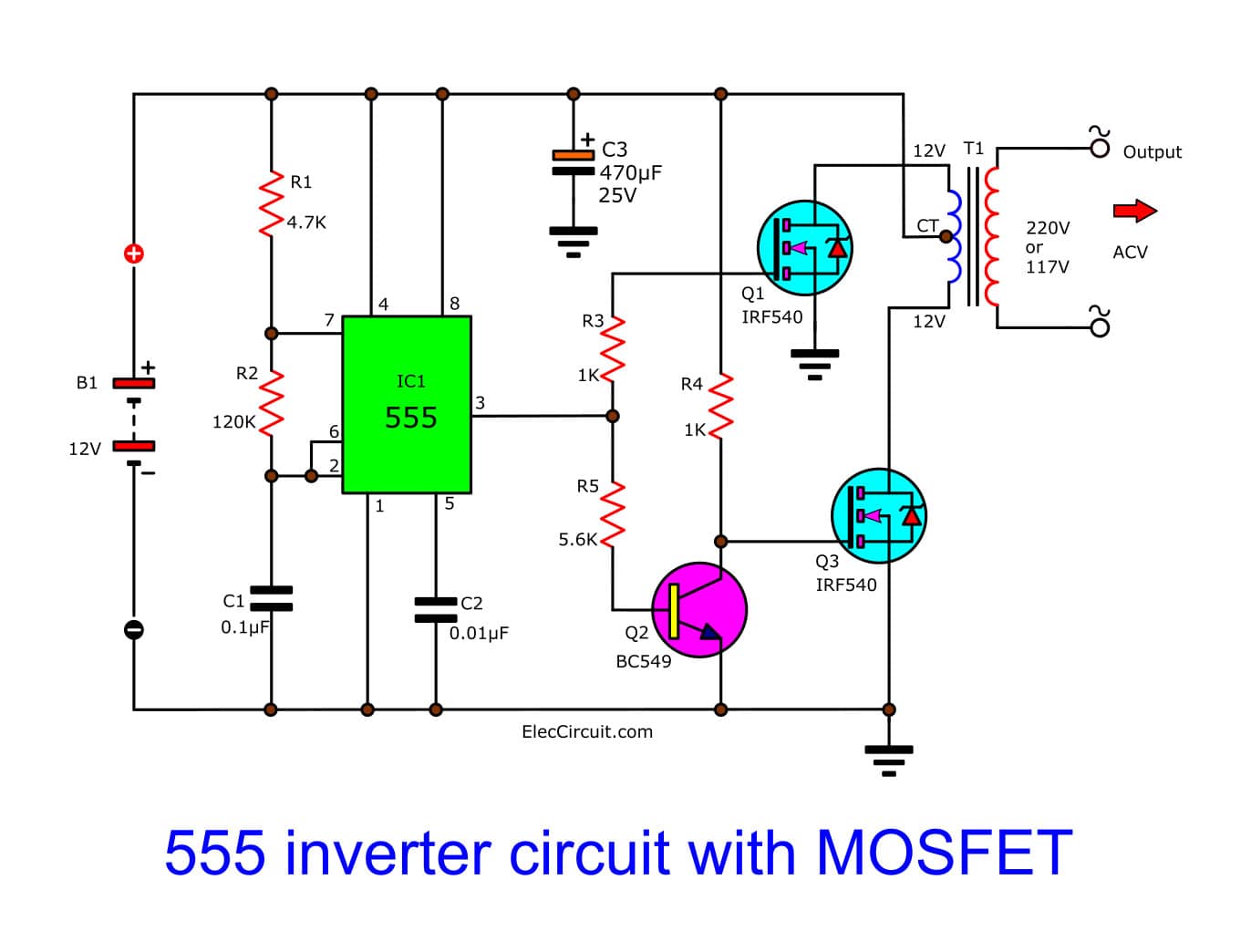
Make Simple 555 Inverter Circuit Using Mosfet Eleccircuit The 555 timer ic is used as the key component which is configured as an astable multivibrator to provide continuous switching pulses. the transformer has 230v 9v is used inverted to act as a step up transformer and is derived by the two transistors tip41a (npn) and tip42a (pnp). the input supply voltage is 5v to 15v dc and the output achieved. The ic 555 inverter circuit is a popular circuit among diyers and engineers alike. it uses a combination of a power transistor, oscillator, and voltage regulator. the power transistor is used to switch the current on and off to regulate the output voltage. the oscillator creates the alternating current while the voltage regulator ensures that. How 555 inverter circuit works. the circuit below is a complete circuit diagram of this project. i use the ic ne555 timer is a square wave frequency generator output of 50hz. the frequency is determined by the r2 resistor and c1 capacitor. 555’s output frequency calculation. if your r2 is 150k, then the output is 47hz. We can create simple small inverter circuit to handle low power devices. the timer ic 555 oscillates high frequency square pulse and the transformer step up the pulse into high ac voltage. this circuit involves in handling of high ac voltage at output that can be lethal, handle with extreme care.

Simplest Power Inverter Circuit Using A Single 555 Ic Circuit Diagr How 555 inverter circuit works. the circuit below is a complete circuit diagram of this project. i use the ic ne555 timer is a square wave frequency generator output of 50hz. the frequency is determined by the r2 resistor and c1 capacitor. 555’s output frequency calculation. if your r2 is 150k, then the output is 47hz. We can create simple small inverter circuit to handle low power devices. the timer ic 555 oscillates high frequency square pulse and the transformer step up the pulse into high ac voltage. this circuit involves in handling of high ac voltage at output that can be lethal, handle with extreme care. The major component in this simple inverter circuit using ic 555 is the timer ic555, which is set as an astable multivibrator to provide a continuous switching pulse. two switching transistors tip41a (npn) and tip42a (pnp) drive the transformer according to the pulse input at the base. t1 is a 230v primary to 9v secondary transformer that is. Use 555 astable multivibrator calculator for frequency output calculations with different value of timing components. this inverter circuit produce pulse frequency from (3 khz to 8 khz) for 20kΩ to 10kΩ range rv1 (variable resistor value). when the power supply applied to this circuit, in ic 555 section, capacitor c1 charges through series.

Comments are closed.