3 Schematic Symbol For Resistor

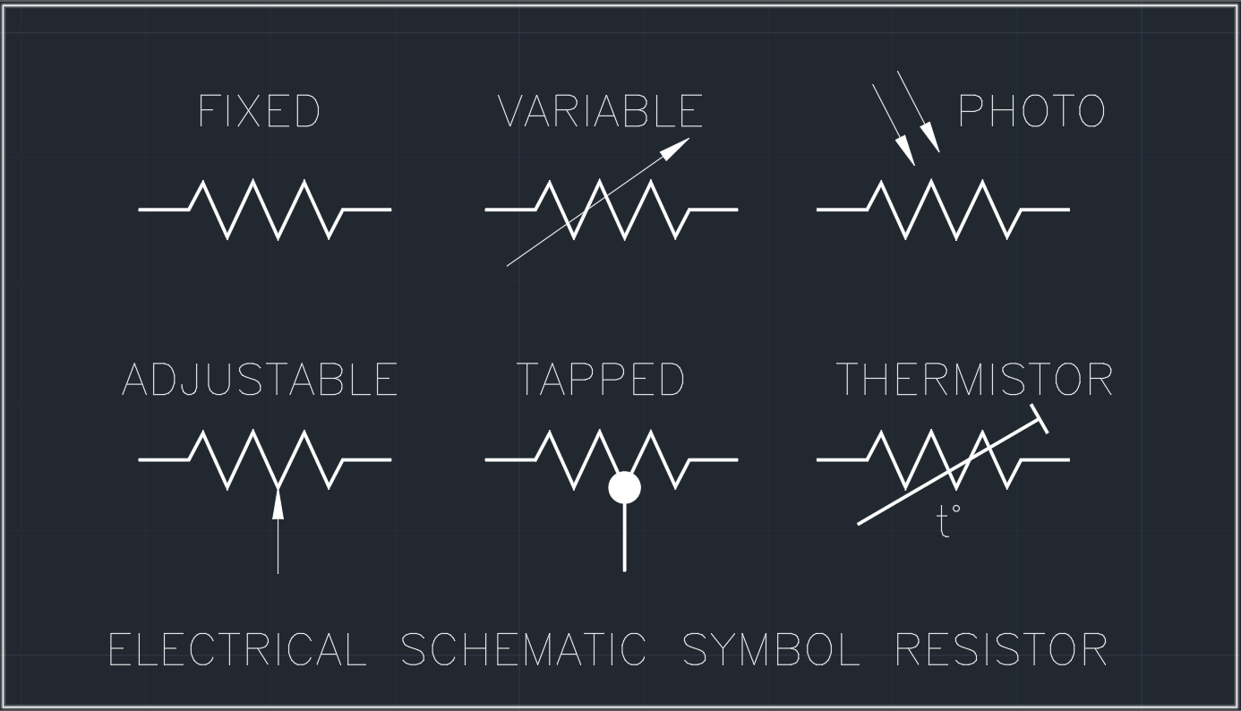
Schematic Resistor Symbols Ground symbols; earth ground: used for zero potential reference and electrical shock protection. chassis ground: connected to the chassis of the circuit: digital common ground : resistor symbols; resistor (ieee) resistor reduces the current flow. resistor (iec) potentiometer (ieee) adjustable resistor has 3 terminals. potentiometer (iec). Resistor schematic symbols and values the most common schematic symbol for a resistor is a zig zag line: resistor values in ohms are usually shown as an adjacent number, and if several resistors are present in a circuit, they will be labeled with a unique identifier number such as r 1 , r 2 , r 3 , etc.

Circuit Diagram Symbol For Resistor Some examples of standards which describe resistor symbols: iec 60617 (international) ansi y32 ieee 315 (us) old. din 40900 (germany) old. as 1102 (australia) old. sometimes the symbol for a particular device is different when it is used in another field of application. for example, different symbols are used in electronics than, for. Electrical & electronic symbols and images are used by engineers in circuit diagrams and schematics to show how a circuits components are connected together. circuit layouts and schematic diagrams are a simple and effective way of showing pictorially the electrical connections, components and operation of a particular electrical circuit or system. 4.7kΩ resistor, and a 5,600,000Ω resistor can be written as 5,600kΩ or (more commonly as) 5.6mΩ. schematic symbol all resistors have two terminals, one connection on each end of the resistor. when modeled on a schematic, a resistor will show up as one of these two symbols: two common resistor schematic symbols. The ability to read electrical schematics is a really useful skill to have. to start developing your schematic reading abilities, it’s important to memorize the most common schematic symbols. each physical component (i.e resistor, capacitor, transistor) has a unique schematic symbol. the main goal of this tutorial is to show you the essential.
.jpg)
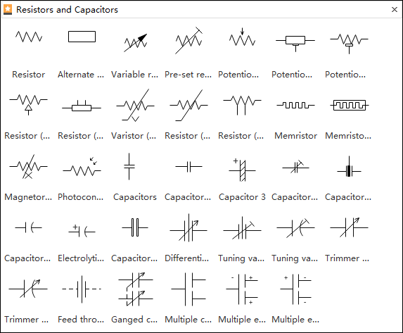
Circuit Diagram Symbol For Resistor 4.7kΩ resistor, and a 5,600,000Ω resistor can be written as 5,600kΩ or (more commonly as) 5.6mΩ. schematic symbol all resistors have two terminals, one connection on each end of the resistor. when modeled on a schematic, a resistor will show up as one of these two symbols: two common resistor schematic symbols. The ability to read electrical schematics is a really useful skill to have. to start developing your schematic reading abilities, it’s important to memorize the most common schematic symbols. each physical component (i.e resistor, capacitor, transistor) has a unique schematic symbol. the main goal of this tutorial is to show you the essential. Each symbol is a visual representation of the component it represents, often resembling the physical appearance or function of the component. some commonly used symbols in an electrical schematic symbols chart include: resistor: represented by a zigzag line. capacitor: represented by two parallel lines. diode: represented by a triangle. This basic schematic symbols chart provides a comprehensive overview of the most commonly used symbols in electrical and electronic circuits. it includes symbols for various components such as resistors, capacitors, diodes, transistors, switches, and more. each symbol is accompanied by a brief description, making it easy to identify and.

Schematic Symbol For Resistor Each symbol is a visual representation of the component it represents, often resembling the physical appearance or function of the component. some commonly used symbols in an electrical schematic symbols chart include: resistor: represented by a zigzag line. capacitor: represented by two parallel lines. diode: represented by a triangle. This basic schematic symbols chart provides a comprehensive overview of the most commonly used symbols in electrical and electronic circuits. it includes symbols for various components such as resistors, capacitors, diodes, transistors, switches, and more. each symbol is accompanied by a brief description, making it easy to identify and.

Schematic Symbol For Resistor

Comments are closed.