3 Pin And 4 Pin Fan Wire Diagrams Cooler Master Faq

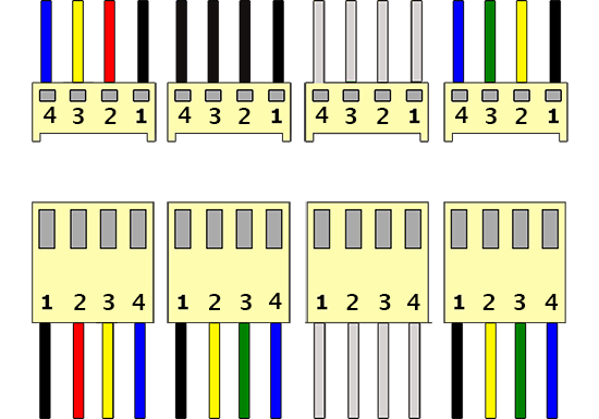
3 Pin And 4 Pin Fan Wire Diagrams Cooler Master Faq 3 pin and 4 pin fan wire diagrams. 3 pin fan connections. *cable coloring varies from fan to fan. pin name. color. color. color. color. 1. 1. the fan connector will have two guides (1) and these will need to line up with the tab (2) that is on the motherboard fan header. 2. next, press down until the fan connector is fully connected to the motherboard header. please note: you can connect a 4 pin fan to a 3 pin or 4 pin header on the motherboard.

3 Pin And 4 Pin Fan Wire Diagrams Cooler Master Faq In this article, we will delve into the basics of a 3 pin fan wiring diagram and explore how it works. a 3 pin fan is a type of cooling fan commonly used in computers. it consists of three wires: the positive ( ) wire, the negative ( ) wire, and the sensor wire. the positive wire supplies power to the fan, while the negative wire is connected. Three wire fan support: ground; pin: 2. three wire fan support: 12 v; pin: 3. three wire fan support: fan tach; pin: n a. three wire fan support: n a; note: when connecting a three wire fan to a four pin fan header, the fan is always on; there is no fan control. four wire fan connecting to a four pin fan header. four wire fan connecting to a. 3. fan spinning at high speed: if your 4 wire computer fan is spinning at high speed constantly, it may indicate an issue with the fan’s speed control. check the fan’s wiring connections and make sure they are properly connected. test the fan in a different system if possible to rule out any compatibility issues. 4. Understanding the wiring diagram of a 3 pin fan is essential for troubleshooting and customization purposes. the three wires found in a 3 pin fan are typically colored black, red, and yellow. the black wire is the ground wire, while the red wire is used to supply power. the yellow wire is for rpm (revolutions per minute) monitoring and control.

Comments are closed.