3 Phase Motor Running In Single Phase Line Circuit

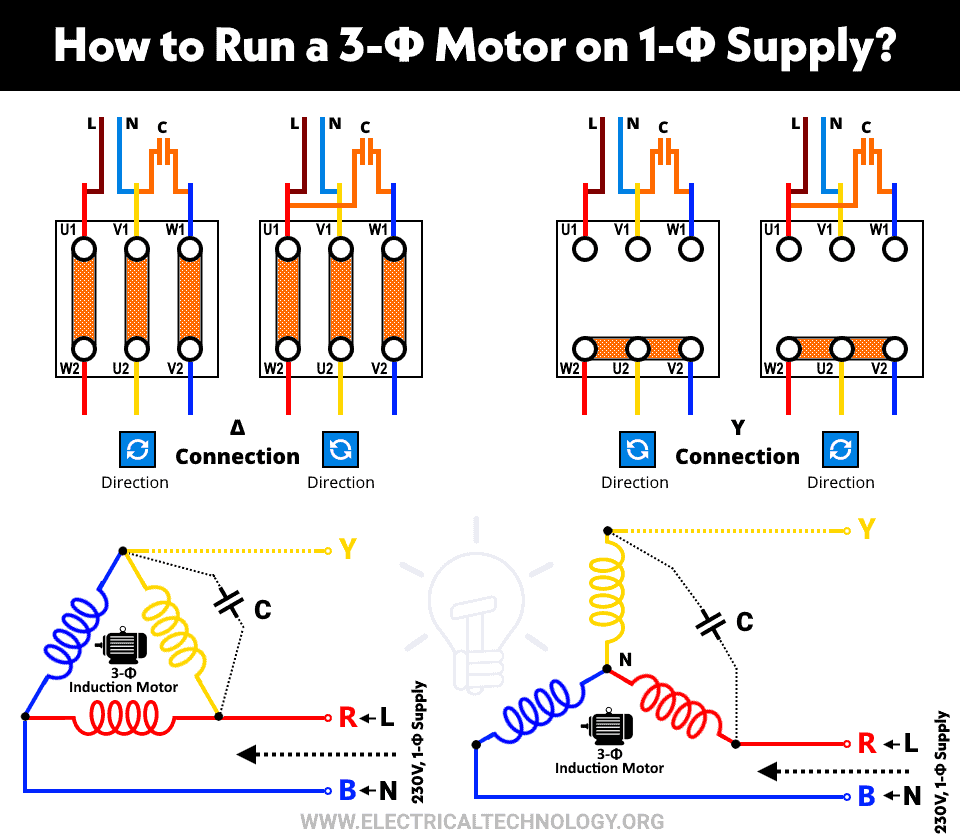
3 Phase Motor Running In Single Phase Line Circuit Because the voltage level of the three phase supply is 400 440 v and the voltage level of the single phase supply is 200 230 v for 50 hz of supply. we can use this circuit without using an autotransformer. in that case, the voltage level remains at single phase power (200 230 v). in this condition also, the motor will run. To connect the power circuit: interconnect the 100 230v ac single phase supply of power that comes from the 2 p mcb to the vfds using two wires labelled “l” (line or phase), “n” (neutral), and ground earth. attach the three phase motor terminals (u 1, v 1, and w 1) to the vfd’s u, v, and w output terminals. check that the phases are.

How To Run 3 Phase Motor In Single Phase Line If one line of a 3 phase induction motor is accidentally opened or if a fuse blows while the motor is running, the eclectic machine will continue to run as a single phase motor. the current drawn from the remaining two lines (phases) will almost double (1.7 to 2.4 times) and the motor will begin to overheat. I show in detail three different methods for powering a three phase motor with single phase power. i show all the parts, how they work together, and the pros. The start capacitor should be 4 to 5 times than running capacitors to match the induction motor high starting current. start capacitor = 50 100µf hp. run capacitors = 12 16µf hp. here the capacitor supplies a synthetic phase approximately midway ∠90 deg between the ∠180 deg single phase power source terminals for starting. 12. i have seen some boxes (with some capacitor circuits inside) which do single phase power supply to 3 phase power supply conversion. the problem with them is that they cause the load motor to heat up, because the phase difference between the legs is 90 degrees instead of 120 degrees. is it possible to design a circuit that produces the third.

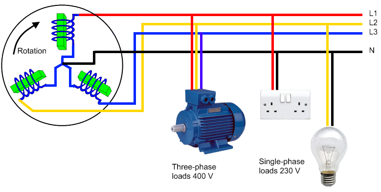
How To Run A Three Phase Motor On Single Phase Power Supply The start capacitor should be 4 to 5 times than running capacitors to match the induction motor high starting current. start capacitor = 50 100µf hp. run capacitors = 12 16µf hp. here the capacitor supplies a synthetic phase approximately midway ∠90 deg between the ∠180 deg single phase power source terminals for starting. 12. i have seen some boxes (with some capacitor circuits inside) which do single phase power supply to 3 phase power supply conversion. the problem with them is that they cause the load motor to heat up, because the phase difference between the legs is 90 degrees instead of 120 degrees. is it possible to design a circuit that produces the third. The contactor should have three main terminals for the three phase power supply (l1, l2 & l3) and three auxiliary contacts for control circuits. install a relay with two sets of contacts, one for forward operation and the other for reverse operation. connect the relay to the control circuit of the contactor. connect the three phase power supply. Understanding its circuit diagram can help in troubleshooting and maintaining such motors. the three phase motor circuit diagram typically consists of three main components: the power supply, the motor, and the control circuit. the power supply provides three phase ac power, which is then fed to the motor. the motor consists of three windings.

Three Phase To Single Phase Converter Circuit Diagram The contactor should have three main terminals for the three phase power supply (l1, l2 & l3) and three auxiliary contacts for control circuits. install a relay with two sets of contacts, one for forward operation and the other for reverse operation. connect the relay to the control circuit of the contactor. connect the three phase power supply. Understanding its circuit diagram can help in troubleshooting and maintaining such motors. the three phase motor circuit diagram typically consists of three main components: the power supply, the motor, and the control circuit. the power supply provides three phase ac power, which is then fed to the motor. the motor consists of three windings.

How To Connect 3 Phase Motor To Single Phase Power Supply 3 P

Comments are closed.