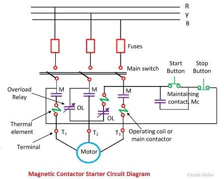
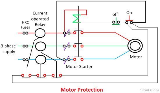
3 Phase Induction Motor Protection

Induction Motor Protection System Circuit Diagram Working Circuit Thermostats thermostats are in built protection devices that are used in protecting an electric motor. with three phase motors, thermostats are considered unstable protection against stall or other rapidly changing temperature conditions. in single phase motors thermostats do protect against locked rotor conditions. Three phase induction motors are accountable for 85 percent of the installed capacity of the industrial driving systems. therefore, the protection of these motors is necessary for the reliable operation of loads. motor failures are mainly divided into three groups: electrical, mechanical, and environmental. mechanical stresses cause overheating.

Protection Of 3 Phase Induction Motor Ppt Webmotor Org Values of each phase are sampled and converted to low ac voltage by means of transformer. more recent research can found by [10 12]. this work presents a pic microcontroller – based digital protection system for three phase induction motor. fault types of induction motordetection like unbalanced voltage, over voltage,. C protection for general purpose low voltage three phase induction motors. the electronic protection has hall transducers and conversion electronic devices for ac currents to dc voltages, ac voltages to dc voltage, temperature to dc voltage, a low capacity plc, swi. ches, motor’s power contactors, and signalling lamps has been developed. In this project, the primary goal is the development of inexpensive and dependable 3 phase induction motor protection systems. phase failure, overheating, and sms alerts should be sent to notify the user of the protection system’s failure. we will keep working to make single phase motor operation even more efficient. The induction motor can be considered a three phase transformer whose secondary, or the rotor, is short circuited and revolves at the motor speed. since the motor usually operates at balanced conditions, only a single phase equivalent circuit is needed. when balanced three phase currents flow in both stator and rotor windings, the resultant.

Induction Motor Protection Circuit Diagram In this project, the primary goal is the development of inexpensive and dependable 3 phase induction motor protection systems. phase failure, overheating, and sms alerts should be sent to notify the user of the protection system’s failure. we will keep working to make single phase motor operation even more efficient. The induction motor can be considered a three phase transformer whose secondary, or the rotor, is short circuited and revolves at the motor speed. since the motor usually operates at balanced conditions, only a single phase equivalent circuit is needed. when balanced three phase currents flow in both stator and rotor windings, the resultant. Motor data. rated output: rated speed: 3583 rpm rated voltage: rated frequency: 60 hertz. rated current: locked‐rotor current: 600 percent. hot stall time: cold overload time: 7 seconds at 100 percent voltage 800 seconds at 2 per‐unit current. service factor: locked‐rotor torque: 55 percent. The objective of this paper is to enhance the 3 phase induction motor protection systems using 16f87 peripheral interface microcontrollers. to ensure protection against motor faults, this paper will comprise of fault analysis using fuzzy logic controller in matlab, use of embedded systems in hardware to protect against faults.

Comments are closed.