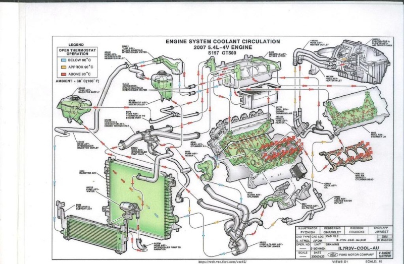
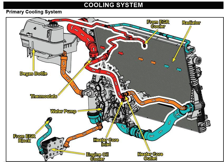
2005 Mustang Gt Cooling System Diagram

Ford Mustang Cooling System Diagram Car Anatomy 303 03a 2 303 03a 3. erationengine coolingnotice:the engine cooling system is filled with motorcra. t premium gold engine coolant. mixing coolant types degrades the corrosion protection of motorcra. system components include t. :block heater (if equipped).engine co. ant temperature (ect) sensor.cooling. an motor. What gets water first, do the heads get it at the same time, etc. there are three different “coolant exits” across the mod motor range. you have what you see on the older 4v stuff which has a coolant pipe coming off of each head, merging into 1 and then entering the radiator. in 2005 the 3v had the double head exit but the ps hose goes.

Ford Mustang Cooling System Diagram Headcontrolsystem 2005 mustang gt cooling system diagram if you’re looking for a 2005 mustang gt cooling system diagram, you’ve come to the right place. this diagram can help you keep your coolant system in top shape, and avoid any potential issues that could arise from neglecting this vital component of your vehicle. First, with the engine off, reach down to the water pump pulley, and gently push the pulley up and down. there shouldn’t be any play or wobble. if there is, that pump is wearing out. as the pump is driven by the belt, check that the accessory belt is in good shape too. if it is cracking, replace the belt. List of elements for 4.0l, cooling fan wiring diagram for ford mustang gt 2005: (in engine control sensor harn, near breakout to egr system module) (in engine control sensor harn, on top of engine) (not used) a c pressure transducer sensor (left front of engine compt) a12. bussed electrical center (bec) (right front of engine compartment) c1035b. Page 37 2005 mustang workshop manual page 37 of 40 measure the resistance between the instrument cluster c220 7, circuit 1410 (tn og), harness side and the repair the circuit. clear the dtcs. repeat the message center switch c253 3, circuit 1410 (tn og), harness side; and between the instrument cluster c220 7, self test.

Ford Mustang Cooling System Diagram Car Anatomy List of elements for 4.0l, cooling fan wiring diagram for ford mustang gt 2005: (in engine control sensor harn, near breakout to egr system module) (in engine control sensor harn, on top of engine) (not used) a c pressure transducer sensor (left front of engine compt) a12. bussed electrical center (bec) (right front of engine compartment) c1035b. Page 37 2005 mustang workshop manual page 37 of 40 measure the resistance between the instrument cluster c220 7, circuit 1410 (tn og), harness side and the repair the circuit. clear the dtcs. repeat the message center switch c253 3, circuit 1410 (tn og), harness side; and between the instrument cluster c220 7, self test. Hot rod staffwriter apr 10, 2013. see all 13 photos. your mustang's cooling system is one of the most basic systems of the internal combustion engine, be it a vintage or a late model mustang. the. Sign up to drive: $100 $500 sign on bonus: partners.uber drive ?invite code=3orknxthe uber man store: ubermanstore sign up to get.

Ford Mustang Cooling System Diagram Hot rod staffwriter apr 10, 2013. see all 13 photos. your mustang's cooling system is one of the most basic systems of the internal combustion engine, be it a vintage or a late model mustang. the. Sign up to drive: $100 $500 sign on bonus: partners.uber drive ?invite code=3orknxthe uber man store: ubermanstore sign up to get.

Comments are closed.